G-25
SM-E2B SERIES, WSM
G GENERAL
[14] CHECK POINTS OF EVERY 3000 HOURS
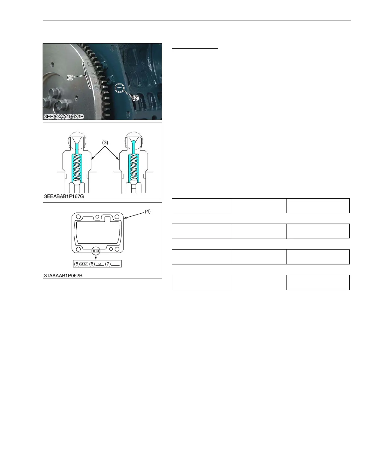
Injection Timing
1. Remove the injection pipes.
2. Remove the engine stop solenoid.
3. Turn the flywheel counterclockwise (viewed from flywheel side)
until the fuel fills up to the hole of the delivery valve holder (3) for
No. 1 cylinder.
4. After the fuel fills up to the hole of the delivery valve holder for No.
1 cylinder, turn back (clockwise) the flywheel around 1.57 rad
(90 °).
5. Turn the flywheel counterclockwise to set at around 0.44 rad
(25 °) before T.D.C..
6. Slowly turn the flywheel counterclockwise and stop turning when
the fuel begins to come up, to get the present injection timing.
7. Check to see the degree on flywheel.
The flywheel has mark “1TC”, “10” and “20” for the crank angle
before the top dead center of No. 1 cylinder.
8. Check to see if the timing angle on the flywheel is aligned with the
alignment mark (2).
9. If injection timing is out of adjustment, readjust the timing with
shims.
Z482/D662/D722-E2B (3600 min
-1
(rpm) spec.)
D782-E2B (3200 min
-1
(rpm) spec.)
Z602/D902-E2B (3200 min
-1
(rpm) spec.)
Z602/D902-E2B (3600 min
-1
(rpm) spec.)
W1023147
Injection timing Factory spec.
0.33 to 0.37 rad (19 to
21 °) before T.D.C.
Injection timing Factory spec.
0.28 to 0.31 rad (16 to
18 °) before T.D.C.
Injection timing Factory spec.
0.30 to 0.33 rad (17 to
19 °) before T.D.C.
Injection timing Factory spec.
0.33 to 0.37 rad (19 to
21 °) before T.D.C.
(1) Timing Line
(2) Alignment Mark
(3) Delivery Valve Holder
(4) Shim (Soft Metal Gasket Shim)
(5) Two-holes : 0.20 mm (0.0079 in.)
(6) One-hole : 0.25 mm (0.0098 in.)
(7) Without hole : 0.30 mm (0.0118 in.)