TRANSAXLE
G23-2, G26-2, WSM
2-M9
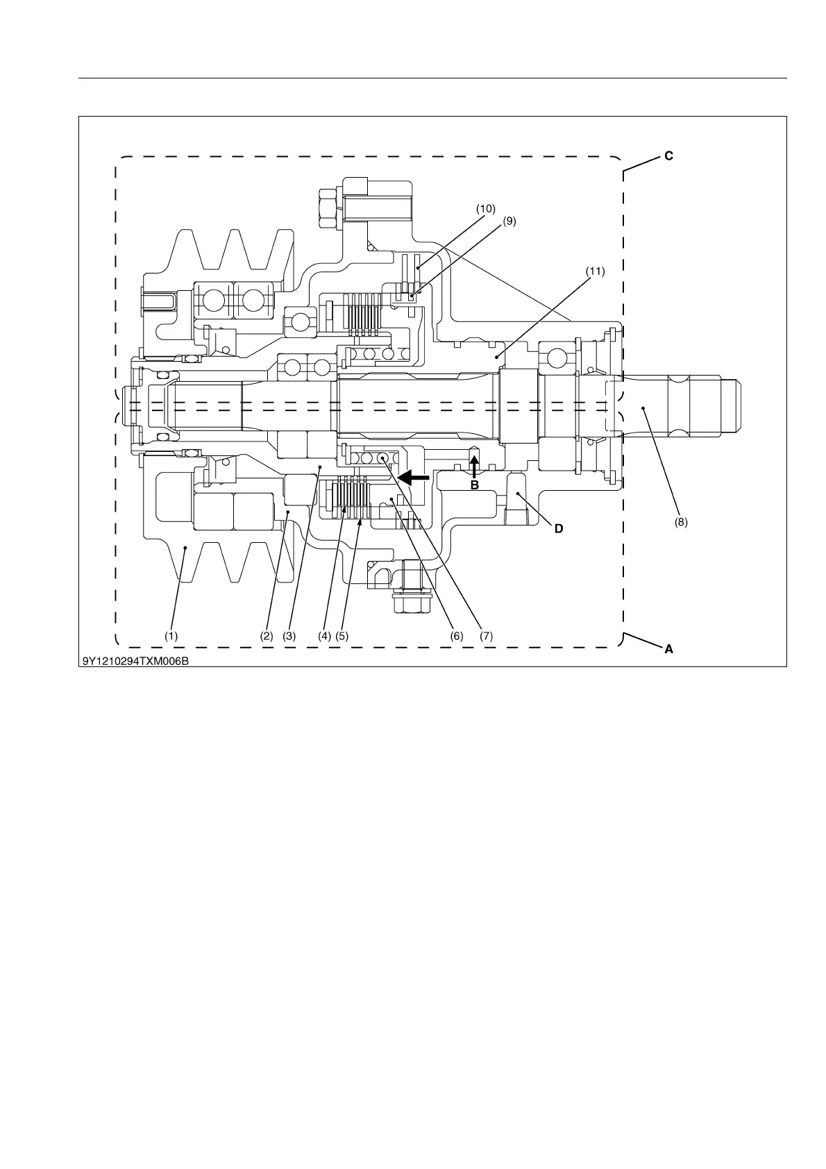
(2) PTO Clutch "Engaged"
This figure shows two functions of PTO clutch "ENGAGED" and "DISENGAGED" positions.
The lower section of this figure shows PTO clutch "ENGAGED" position.
When the PTO lever is set to "ENGAGED" position, the pressurized hydraulic oil flows into the PTO clutch
assembly. This high pressurized hydraulic oil pushes the clutch piston (6), the brake spring (7), the disk plates (4) and
the separate plates (5).
And the engine power is transmitted from the pulley (1), through the spline boss (3), the disk plates (4), the
separate plates (5) and the PTO clutch case (11) to the front PTO shaft (8).
9Y1210892TXM0009US0
(1) Belt Driven Pulley
(2) Front Case
(3) Spline Boss
(4) Disk Plate
(5) Separate Plate
(6) Clutch Piston
(7) Brake Spring
(8) Front PTO Shaft
(9) Brake Plate
(10) Brake Disk
(11) PTO Clutch Case
A: PTO Clutch "Engaged"
B: High Pressurized Hydraulic
Oil from PTO Clutch Control
Valve
C: PTO Clutch "Disengaged"
D: Oil Passage to Oil Tank in
PTO Clutch

 Loading...