ELECTRICAL SYSTEM
G23-2, G26-2, WSM
6-S11
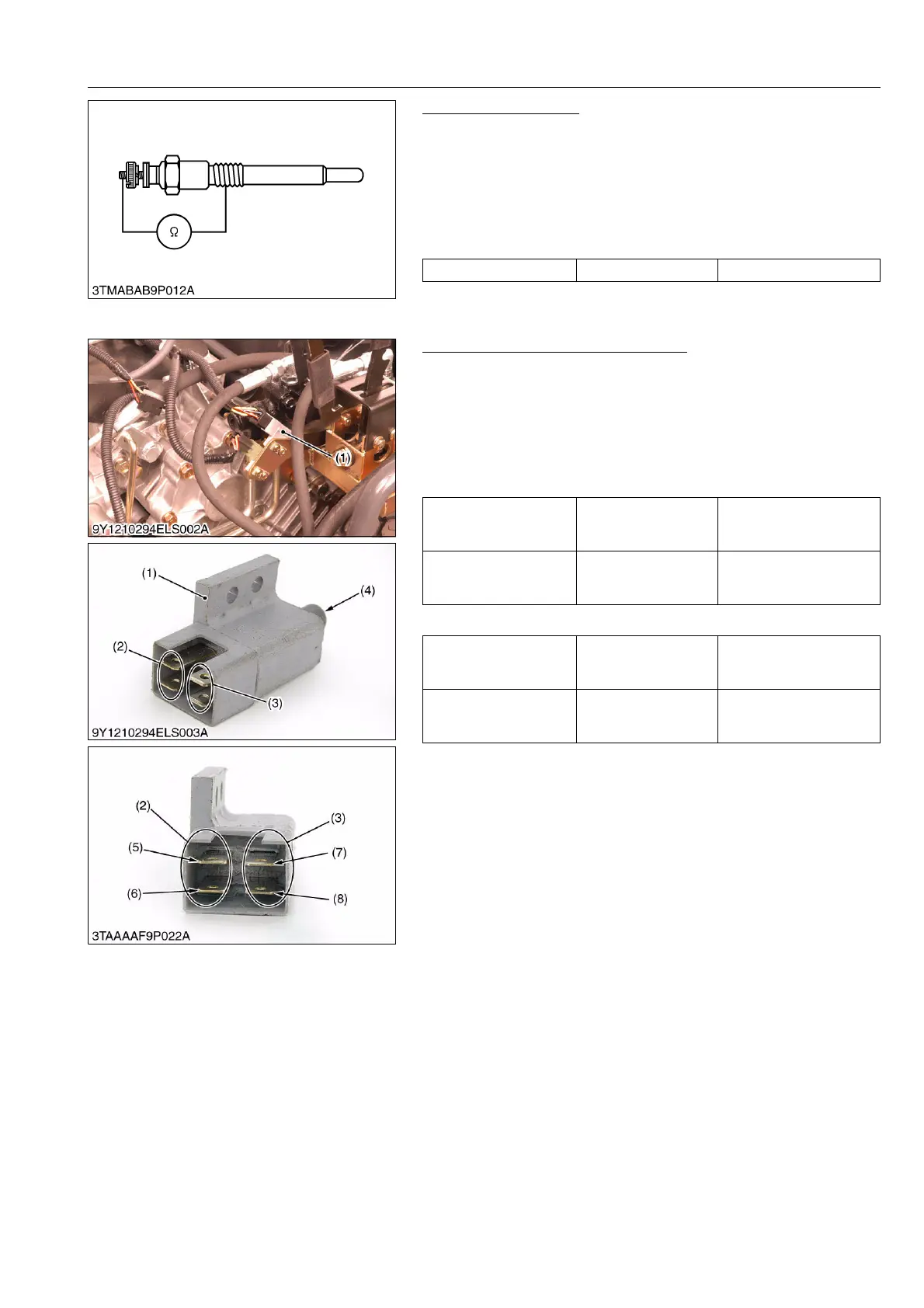
Glow Plug Continuity
1. Disconnect the lead from the glow plugs.
2. Measure the resistance between the glow plug terminal and the
chassis.
3. If 0 ohm is indicated, the screw at the tip of the glow plug and
the housing are short-circuited.
4. If the factory specification is not indicated, the glow plug is
faulty.
WSM000001ELS0012US0
(5) Safety Switch
PTO Shift Lever Switch 1 Continuity
1. Remove the left rear wheel.
2. Remove the PTO shift lever switch (1).
3. Measure the resistance with an ohmmeter across the switch
terminals.
4. If the resistance values specified below are not indicated, the
safety switch is faulty.
Plunger is pushed into the switch body
Plunger is released
9Y1210892ELS0011US0
Glow plug resistance Factory specification Approx. 0.9 Ω
Resistance
1 terminal (5) –
2 terminal (6)
Factory specification 0 Ω
Resistance
3 terminal (7) –
4 terminal (8)
Factory specification 0 Ω
Resistance
1 terminal (5) –
2 terminal (6)
Factory specification Infinity
Resistance
3 terminal (7) –
4 terminal (8)
Factory specification Infinity
(1) PTO Shift Lever Switch
(2) 2P Connector (LH)
(3) 2P Connector (RH)
(4) Plunger
(5) 1 Terminal
(6) 2 Terminal
(7) 3 Terminal
(8) 4 Terminal

 Loading...