ELECTRICAL SYSTEM
G23-2, G26-2, WSM
6-M7
5. GAUGES
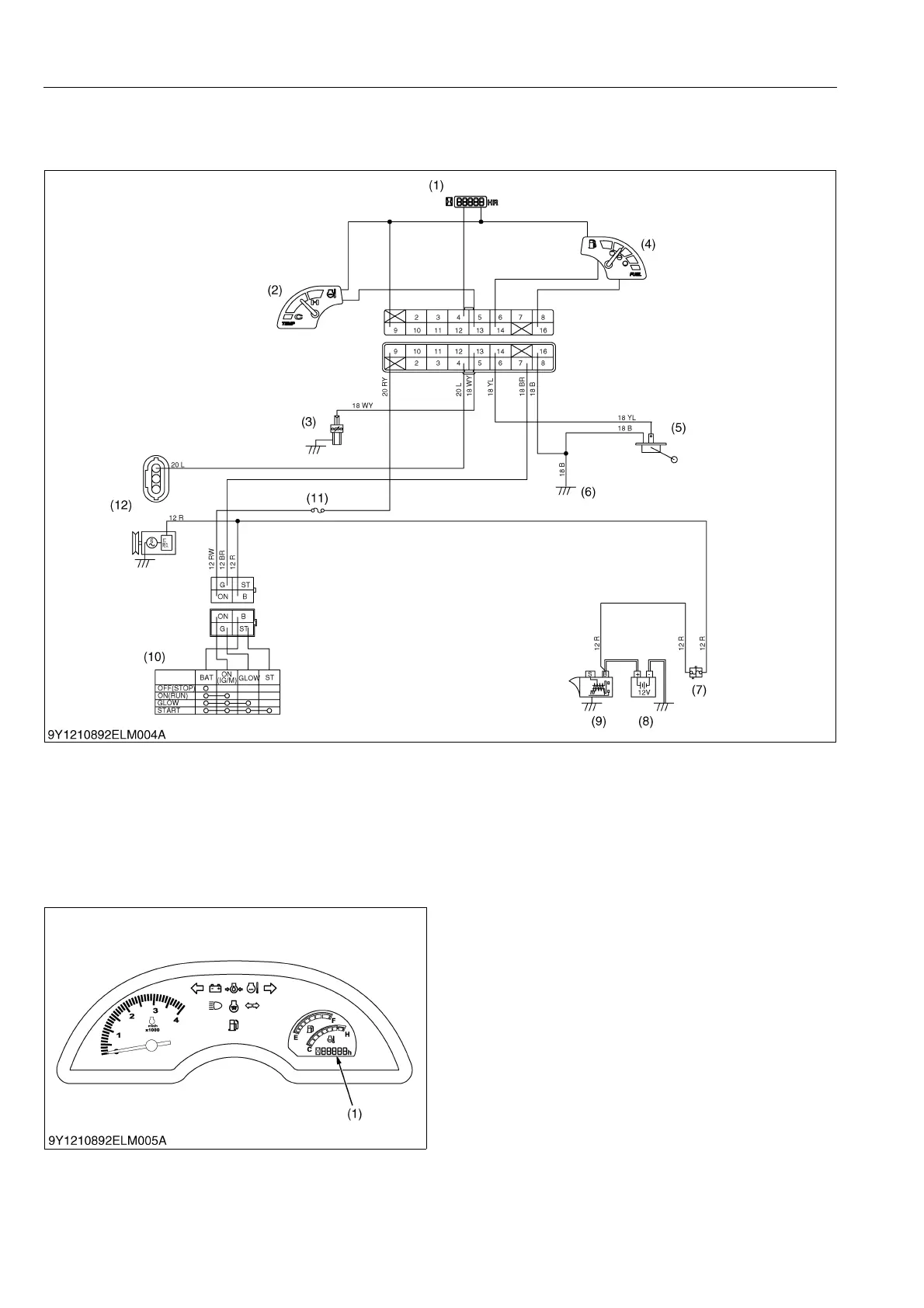
[1] ELECTRICAL CIRCUIT
The fuel quantity is indicated by the fuel gauge. The coolant temperature is indicated by the coolant temperature
gauge.
9Y1210892ELM0007US0
[2] HOUR AND TACHOMETER
The electrical hour meter and tachometer is
equipped on the meter panel.
This meter indicates the operated hours when the
main switch is turned to "ON" position.
After starting the engine, this meter indicates the
present engine revolution.
The meter picks up the voltage from the IC regulator
located in the alternator.
The IC regulator sends a signal of the engine
revolution to the meter.
The meter calculates the signal. It changes and
indicates the signal to the engine revolution in
cooperation with the voltage.
9Y1210892ELM0008US0
(1) Hour and Tachometer
(2) Coolant Temperature Gauge
(3) Thermo Unit
(4) Fuel Gauge
(5) Fuel Sensor
(6) Frame Earth
(7) Slow Blow Fuse
(8) Battery
(9) Starter Motor
(10) Main Switch
(11) Fuse
(12) Alternator
(1) Electrical Hourmeter and
Tachometer

 Loading...