7-S7
M6800 · M6800S · M8200 · M9000, WSM
STEERING
Disassembling Power Steering Hydraulic Pump
[Combined Flow Type]
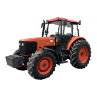
1. Put parting mark (A), (B), on the flange (3), housing (8) and
housing cover (11).
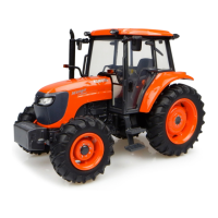
2. Remove the housing cover (11) and housing (8).
3. Remove the backup elements (5).
4. Take out the bushings (6), (9) and gears (7), (13).
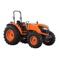
(When reassembling)
• Install the driven gear (13), noting its direction as shown in the
figure.
• When installing the bushings (6) and (9), be sure to reassemble
them to the each original position.
• Take care not to damage the seal elements and O-rings.
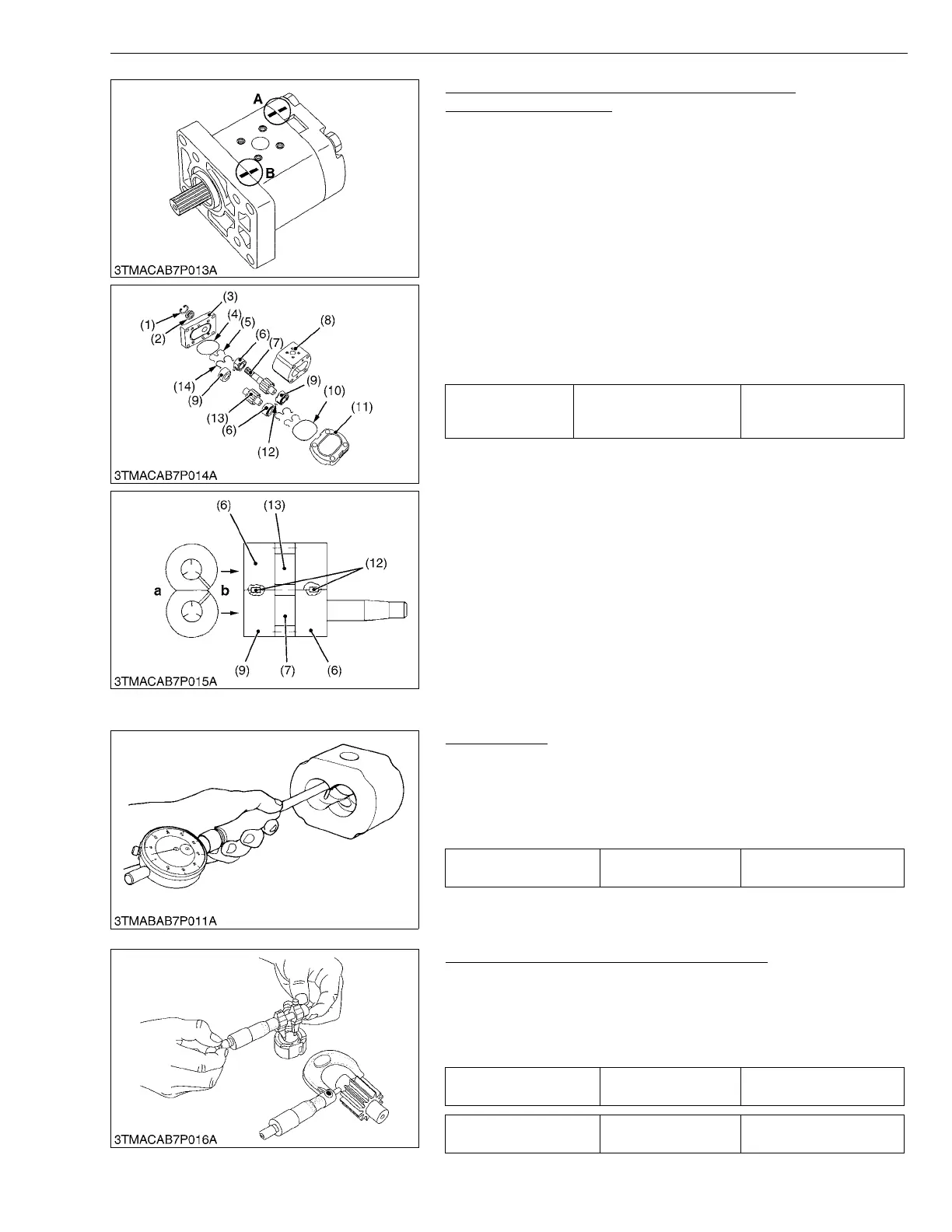
• After reassembly, check the smooth rotation of the hydraulic
pump (for example, mount arm an approx. 100 mm (3.94 in.) long
to the drive gear and rotate its arm slowly for smooth rotation).
W1013304
(3) Servicing
Housing Bore
1. Measure the housing I.D. where the interior surface is not
scratched, and measure the housing I.D. where the interior
surface is scratched.
2. If the values obtained in the two determinations differ by more
than the allowable limit, replace the hydraulic pump as a unit.
(Reference)
• Use a cylinder gauge to measure the housing I.D..
W1013805
Clearance between Bushing and Gear Shaft
1. Measure the gear shaft O.D. with an outside micrometer.
2. Measure the bushing I.D. with an inside micrometer, and
calculate the clearance.
3. If the clearance exceeds the allowable limit, replace the gear
shaft and the bushing as a unit.
W1013925
Tightening torque
Housing cover mounting
screw
39.2 to 44.1 N·m
4.0 to 4.5 kgf·m
28.9 to 32.5 ft-lbs
(1) Internal Snap Ring
(2) Oil Seal
(3) Flange
(4) O-ring
(5) Backup Element
(6) Bushing
(7) Drive Gear
(8) Housing
(9) Bushing
(10) O-ring
(11) Housing Cover
(12) Key
(13) Driven Gear
(14) Seal Element
A : Parting Mark
B : Parting Mark
a : Inlet
b : Outlet
Depth of scratch Allowable limit
0.09 mm
0.0035 in.
Clearance between
bushing and gear shaft
Allowable limit
0.15 mm
0.0059 in.
Gear shaft O.D. Allowable limit
17.968 mm
0.7074 in.
 Loading...