8-S13
M6800 · M6800S · M8200 · M9000, WSM
HYDRAULIC SYSTEM
[2] POSITION CONTROL AND DRAFT CONTROL LINKAGE
(1) Checking and Adjusting
(A) M6800(S)
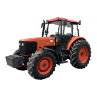
Adjusting Uppermost Position of Lift Arm
1. Attach the weight (1) of 490 N (50 kgf, 110 lbs) to the end of lower
link (2).
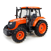
2. Set the position control lever (3) and draft control lever (4) to the
lowest position.
3. Start the engine, and set the engine speed at the 1000 min
−1
(rpm).
4. Set the position control lever (3) to the uppermost position.
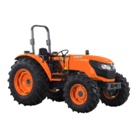
5. Shorten the feedback rod by turning the turnbuckle (5) until the
relief valve begins to be operated.
6. From the feedback rod position obtained above 5, turn the
turnbuckle by 1.5 turn to lengthen the feedback rod, then tighten
the lock nut.
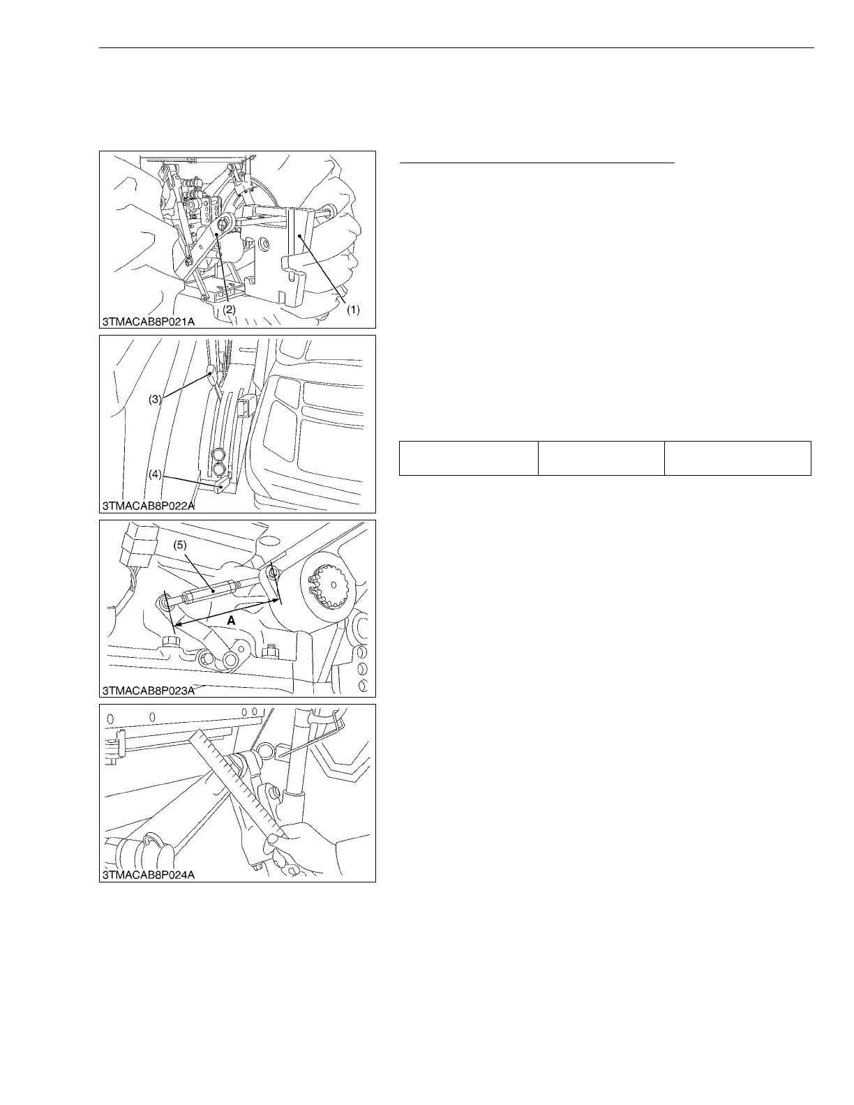
7. Move the position control lever down then all the way up. Stop
the engine and check that the lift arm has 5 to 20 mm (0.20 to
0.79 in.) play upward on its edge.
8. If the specified play is not obtained, repeat from 4 again.
W1018250
Position control
feedback rod A
Factory spec.
Approx. 125 mm
4.92 in.
(1) Weight
(2) Lower Link
(3) Position Control Lever
(4) Draft Control Lever
(5) Turnbuckle
 Loading...