Do you have a question about the Kubota U20-3 and is the answer not in the manual?
Locates and identifies machine and engine serial numbers for service reference.
Details essential safety measures for maintenance and repair operations, covering work clothes, tools, and team coordination.
Outlines crucial safety steps and critical functional processes like adhesive use and electrical connections.
Lists key items to inspect after reassembly, such as noise, vibrations, decals, and fluid levels.
Covers basic principles for servicing, including tightening torques, adhesive application, and hydraulic system precautions.
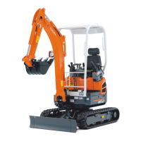
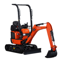
Provides detailed specifications for machine size, weight, performance, and attachments.
Outlines recommended service intervals for various maintenance tasks based on operating hours and time.
Details technical specifications for the U20-3 and U25-3 excavators, including dimensions and engine data.
Information on component compatibility and dimensions, specifically for the bucket.
Explains the internal structure and linkage of machine components like control levers and engine mounts.
Details machine specifications including weight for different configurations.
Comprehensive table of machine specs: engine, dimensions, performance, attachments.
Details stroke and operating force for control levers and pedals.
Provides detailed dimensions for front pins and buckets.
Provides critical safety instructions and procedures for crawler replacement and tension adjustment.
Details dimensional specs and service data for the U20-3 variable track system.
Identifies and labels parts of the front attachment assembly.
Explains assembly and adjustment for control levers and pedals.
Instructions for installing cabin or canopy, including mounting procedures and torques.
Guides on swivel bearing, grease tubes, track tension device, and rollers.
Introduces the 05-M series engine, highlighting technologies and benefits.
Describes the construction of cylinder block, head, crankshaft, pistons, rods, camshafts, and flywheel.
Provides an overview of the lubricating system, including oil pump and filter.
Explains the cooling system components like radiator, water pump, and thermostat.
Details the air cleaner and muffler systems for intake and exhaust.
Covers the fuel system, including injection pump, nozzle, filter, and governor.
Describes the charging system, including alternator and IC regulator.
Explains the turbocharger's mechanism, advantages, and checking procedures.
Guides on mounting the engine, including bracket assembly and tightening torques.
Covers engine identification, general precautions, tightening torques, and troubleshooting.
Procedures for checking, adjusting, disassembling, and assembling engine body parts.
Details checking and servicing procedures for the engine's lubricating system.
Covers checking and disassembly/assembly procedures for the cooling system components.
Provides procedures for checking, adjusting, and disassembling fuel system components.
Covers checking, disassembly, assembly, and servicing of electrical system components.
Explains checking and disassembly/assembly procedures for the turbocharger system.
Outlines key features and improvements in the hydraulic system design.
Provides detailed specs for hydraulic components like pumps, valves, and motors.
Details the main pump's structure, specifications, performance curves, and operating principles.
Covers control valve specifications, general view, sectional views, and circuit functions.
Explains the pilot valve's structure, control diagram, and functions.
Details the swing motor's structure, specifications, operating principle, and brake function.
Shows component parts and layout for fixed and retractable undercarriage swivel joints.
Outlines structure and specifications for the U20-3 travel motor.
Details structure, specifications, and operating principles for the U25-3 travel motor.
Provides hydraulic circuit diagrams for fixed and retractable undercarriages.
A guide to diagnose and resolve common engine and hydraulic system issues.
Lists detailed specifications for hydraulic components like pumps, relief valves, and cylinders.
Covers testing procedures for pump flow, pressure, drain, operating speed, and component performance.
Step-by-step instructions for disassembling and reassembling hydraulic system components like pumps and valves.
Illustrates the layout of electrical components and harness routing on the machine.
Explains the function of the main electrical circuits, including battery, safety relay, and auto glow.
Details the auto glow circuit's function, timer values, and operating pattern.
Describes the fuel control circuit, including components like the fuel sensor and residual sensor.
Explains the engine oil pressure sensor circuit, including its normal and trouble conditions.
Details the structure and function of the horn circuit, including current flow and diode purpose.
Illustrates the electrical diagrams for the cab, working lights, heater, and other auxiliary systems.
Explains the meter panel circuit diagram, connectors, and operation of indicator lamps.
Describes the heater circuit's current flow, electromagnetic braking, and purpose of the relay.
Troubleshooting guide for travel hi-speed malfunction, covering electrical and hydraulic system checks.
Provides precautions for clamping electric wires and details on harness-fixed clamps.
Troubleshooting guide for engine, meter panel, and other electrical system issues.
| Tail Swing Type | Conventional |
|---|---|
| Engine Gross Power | 24.5 kW |
| Max Reach at Ground Level | 4, 490 mm |
| Max Dumping Height | 2, 480 mm |
| Travel Speed | 2.5 km/h |