U20-3, U25-3 WSM Hydraulic system (Mechanism section)
IV-M-26
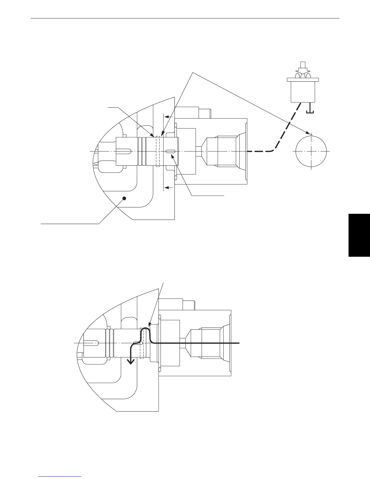
i. Automatic air bleeding in hydraulic pilot section
Automatic air bleeding mechanism is provided at the control valve spool which is operated by hydraulic
pilot valve.
(1) When the spool of the control valve is at neutral position.
(2) When the spool of the control pilot valve is moved in full stroke.
B
V-groove equivalent to 0.25 dia.
End-milled portion
Section A-A
A
A
Control valve, passage to tank
When the spool is at neutral position, air is blocked at the position B
as shown in the figure above and the air in the hydraulic pilot circuit
does not return to the tank.
Hydraulic
pilot valve
When the spool is moved in full stroke, the
air bleeding section opens as shown in the
figure, and the air in the hydraulic pilot circuit
goes up to the tank through the V-groove,
end-milled portion and passage to the tank.
V-groove equivalent to 0.25 dia.

 Loading...