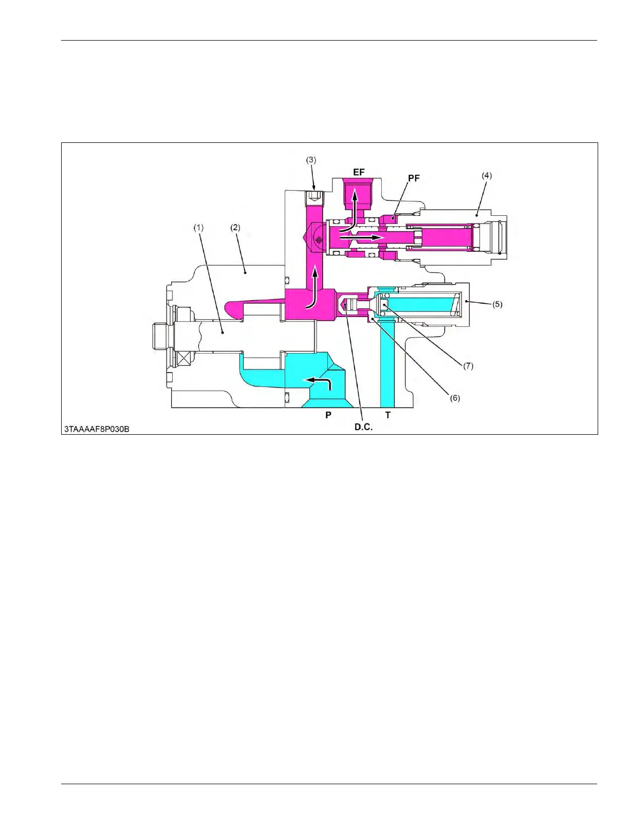
6.2 Structure of relief valve
Among direct acting
relief valves, this type is suited to higher pressure and has large capacity. Furthermore, this type
is free from unstable operation, such as chattering, which occurs often in direct acting relief valves.
As shown in the figure, the guide is attached to the poppet (7) and a valve chamber D.C. (called the damping
chamber) is formed at the top of the guide piston. The inlet of the valve leads to the chamber via a clearance between
the sliding portion of the guide and the seat (6), minimizing valve vibration with the damping effect of the chamber.
(1) Hydraulic pump gear
(2) Hydraulic pump case
(3) Plug
(4)
Flow priority valve
(5) Relief valve
(6) Seat
(7) Poppet
EF: EF port (to 3 point hitch con-
trol circuit)
PF: PF port (to power steering,
PTO clutch and HST circuit)
DC: Damping chamber
P: Pump port (Suction)
T: Tank port
MECHANISM
6. Relief valve 7. HYDRAULIC SYSTEM
BX1880,BX2380,BX2680,RCK60B-23BX,RCK54-23BX,RCK48-18BX,RCK60D-26BX,RCK54D-26BX
 Loading...