Putting into service
Disc mower
GMD240-280-310
35
KN204AGB H
Preparing the machine
Linkage adjustment
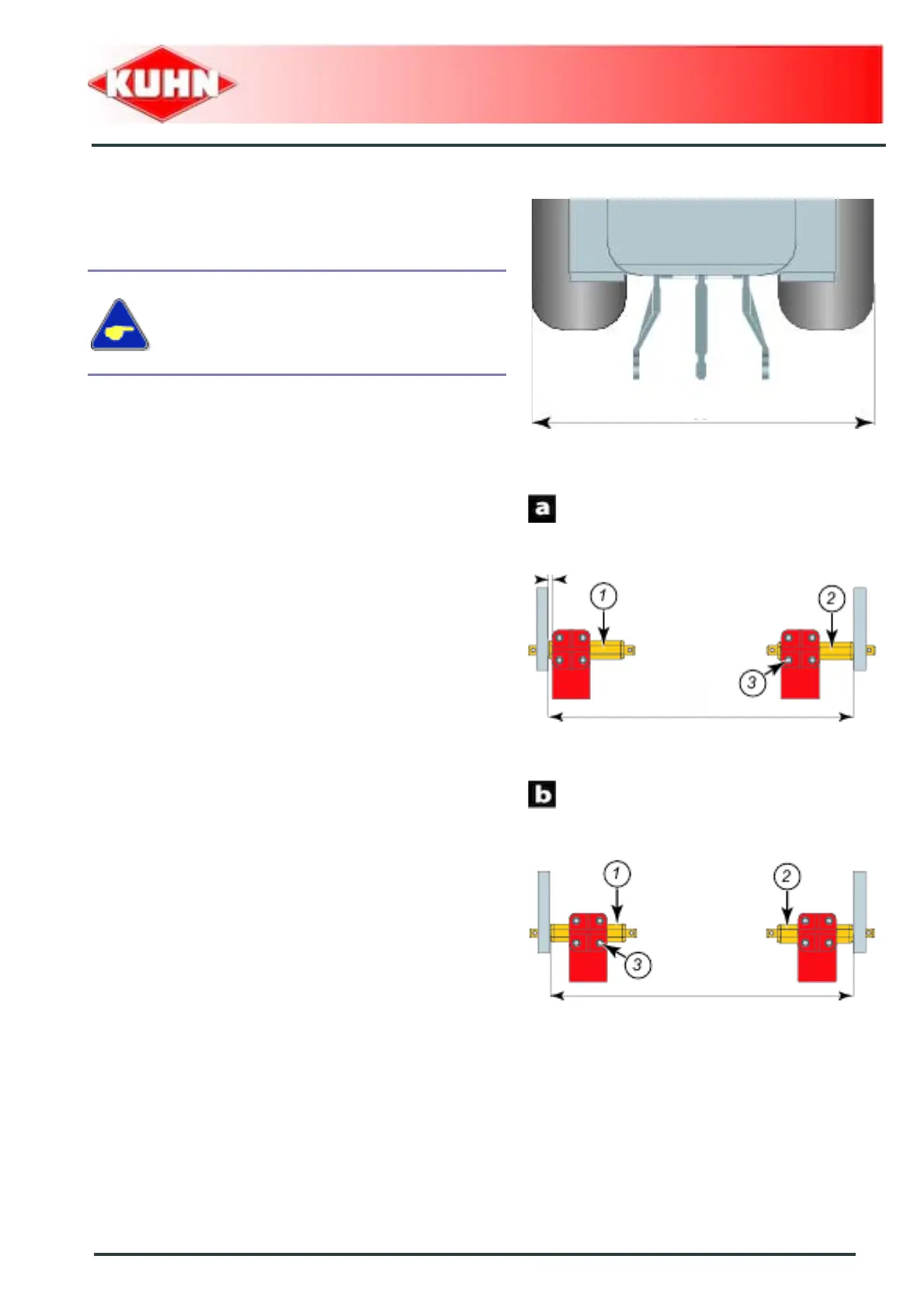
- Measure dimension A.
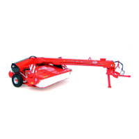
If measure A is below 2.10 m (6’11’’):
- Place lower links in position a.
- Adjust machine lower hitch pin position:
• Loosen the 8 screws (3).
• Position hitch pin (1) at measure F = 10 mm (0.4").
• Tighten 4 hitch pin screws (1): Torque : 12.3 daN m
(91 lbf ft).
• Position hitch pin (2) at measure X = 825 mm (2’8").
• Tighten 4 hitch pin screws (2): Torque : 12.3 daN m
(91 lbf ft).
If measure A is comprised between 2.10 m (6’11")
and 2.25 m (7’04"):
- Place lower links in position b.
- Adjust machine lower hitch pin position:
• Loosen the 8 screws (3).
• Centre hitch pin (1) with regards to the mounting
plate.
• Tighten 4 hitch pin screws (1): Torque : 12.3 daN m
(91 lbf ft).
• Position hitch pin (2) at measure X = 825 mm (2’8").
• Tighten 4 hitch pin screws (2): Torque : 12.3 daN m
(91 lbf ft).
When optional equipment is used, follow
specific procedures mentioned in the related
section:
• Optional equipment / Longer hitch
pins.