Kvaser U100 User’s Guide 9 (22)
4 Appendices
In this section you will find technical information about the Kvaser U100 and its
connectors.
4.1 Definitions of LED states and colors
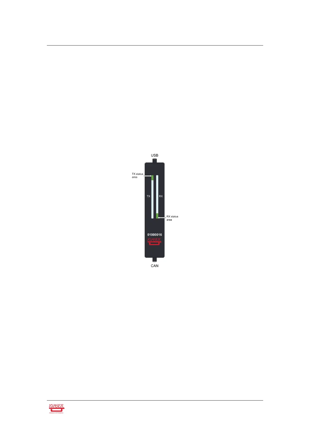
The Kvaser U100 has one Tx LED Bar and one Rx LED Bar. Each LED Bar has a
status area, the Tx LED Bar has a status area towards the USB end of the bar, and
the Rx LED bar has a status area towards the CAN end of the bar. This is shown in
Figure 2.
Figure 2: The Tx and Rx LED bars on the Kvaser U100 includes status areas.
The Tx LED bar lit area grows from the USB end of the LED bar towards the CAN
end of the bar as CAN Tx traffic is increased. Likewise, the Rx LED bar lit area
grows from the CAN end of the LED bar towards the USB end of the bar as the
message rate of the received traffic is increased, see Figure 3 on Page 10. In this
example the unit is transmitting data, which shows a yellow Tx status area. No
CAN traffic is received and as such the Rx status area is green.
The total size of the LED bars are indicating the current bus load, e.g. Figure 3 on
Page 10 shows only receiving CAN messages at 50% bus load. Figure 4 on
Page 10 shows two different bus load conditions. The image on the left shows the
unit transmitting and receiving data corresponding to 50% bus load in each
direction for a total of 100% bus load. The image on the right shows the unit
transmitting data corresponding to 100% bus load.
Kvaser AB, Mölndal, Sweden — www.kvaser.com