SECTION III
Adjustments
P 3.7
L. CAM ASSEMBLY:
The cam assembly drives the pick through its cycle
and raises the closure stop at the proper time to
stop the closure strip so the leading closure can be
separated from the remaining strip. The closer cam
fastens to the outside edge of the cam hub. The
switch cam contacts the cam switch stopping the
motor and cam assembly when the pick is in the
parked or neutral position (Figure 3.13). The cam
assembly should remain on the motor shaft with no
need for adjustment. If however the cam assembly
is disassembled the following information is helpful
to reassemble it.
The cam is adjusted to drive either an 086A Model
100 or 086A Models 200, 300, and 400. Correct
assembly of the components provide the required
pick stroke so the closer functions properly. Align
the cam to the hub as follows:
1. Hold the cam so the stamped letter “R” is on the
correct side for your model closer as shown in
the appropriate view in Figure 3.11
2. Position the hub behind the cam. Rotate the
hub until one of the two 8-32 tapped holes in the
hub aligns with the countersunk hole in the cam.
3. Insert the flat head screw to secure the two
parts.
4. If the switch cam has been removed, remount it
after the cam and hub have been connected.
Square up the switch cam to the main cam hub
and then tighten into place (Figure 3.12).
5. Install the cam assembly onto the motor shaft.
Refer to part L below.
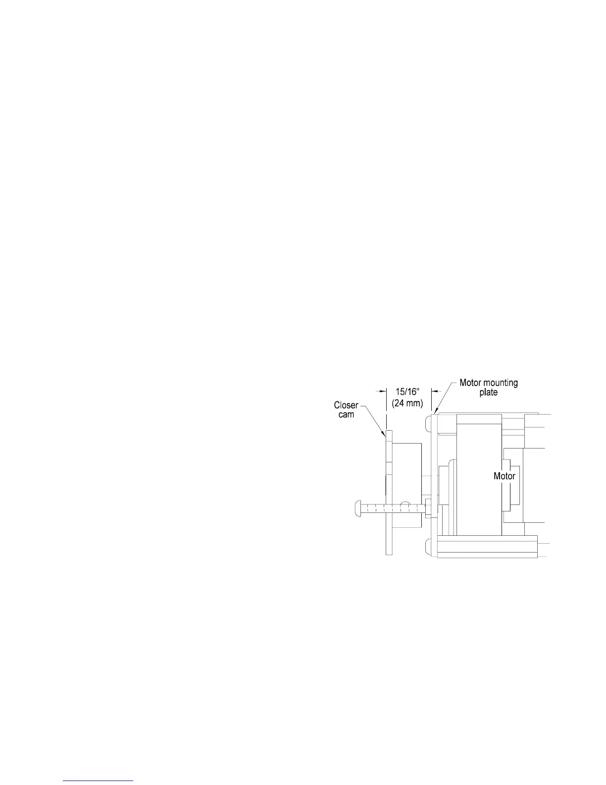
M. CAM ASSEMBLY LATERAL ALIGNMENT:
1. Set the lateral (side to side) position of the cam
assembly so the outside edge of the closer cam
measures 15/16” (24mm) from the outside edge
of the motor plate (Figure 3.12).
2. Rotate the cam assembly to position the set
screw over the flat on the motor shaft and
tighten the set screw. The angular position of
the cam assembly is not important because the
motor will stop with the cam in the correct
position when the switch cam contacts the limit
switch.
3. Tighten the set screw.
086A 08 08
Figure 3.12
 Loading...