Page 11
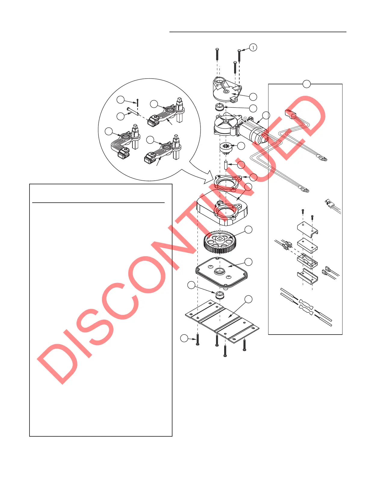
Step Motor Assembly Diagram
This view of the motor is rotated 180° of actual orientation
to the step frame.
LINKAGE
ASSEMBLIES
TWO-WAY CONNECTORS
TO THE CONTROL UNIT
Clamp
Style with
Spade
Connectors
Insulated
Butt
Connectors
Packard Style
Connector
Adapter
Pigtail
8
2
3
4
5
6
10
11
12
13
3
14
9
7B
Drive link shaft
extension length = 2 7/16"
Drive link shaft
extension length = 2 9/16"
7C
7A
16
15
PARTS KEY
Part# Description
1 #10 x 1 3/4” self-tapping hex washer-head screw
2A Motor bearing bracket
2B Motor bearing bracket (standard-- not shown)
3 Bearing
4A Motor
4B Motor (high-torque, use with 23 & 40 Series steps)
5A Adaptor gear
5B Adaptor gear (for AM motor -- not shown)
6 Adaptor gear shaft
7A Linkage assembly
7B Linkage assembly
7C Linkage assembly
8 Cotter pin
9 Clevis pin
10 Gear case
11 Gear
12 Gear case cover
13 Motor mounting plate
14 1/4-20 x 1 1/4’’ tri-lobal thread forming screw
15 Motor gear case adapter
16A Adapter pigtail (standard)
16B Adapter pigtail (high-torque)