Page 7
Step Test Procedures
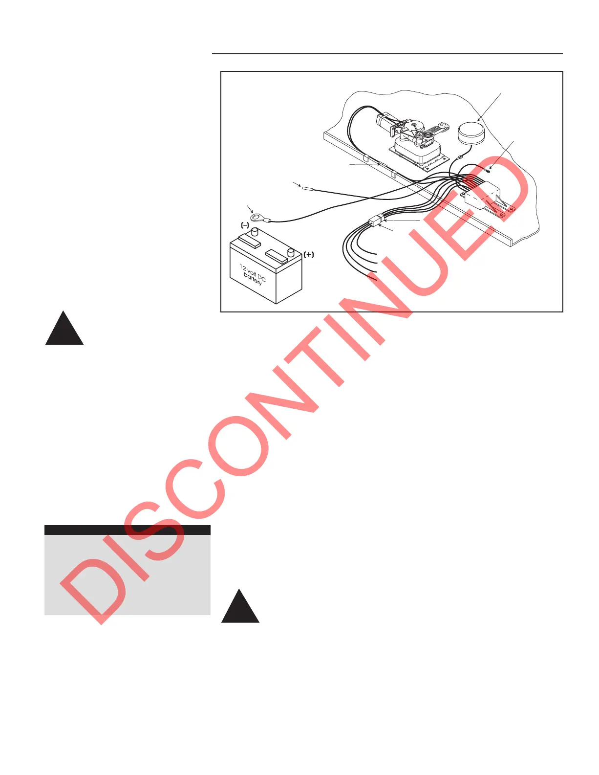
FIGURE 5: Step test procedures wiring diagram
IMPORTANT
INSTALLER NOTES:
Kwikee recommends wiring the
step to the vehicle battery instead
of the “house” battery due to
potential interference from other
circuits.
Step controls require grounding
prior to installation of the positive
12 volt connections.
All Circuits noted as requiring
fuses must be fused. Fuses should
be located as close as practical to
the pwer source in order to
provide maximum protection to the
wiring circuits. Failure to provide
required fuses may void warranty.
NOTE: Prior to connecting any
wiring, disconnect the vehicle’s power
source at the battery.
1. Ground the control unit by
attaching the long green ground wire
from the control unit to the chassis (see
Figure 2 for all wiring details). For steps
with door switch only operations, follow
the wiring schematic illustrated in
Figure 3.
NOTE: A good ground connection is
required for proper step operation. To
insure a good ground connection
(metal-to-metal), scrape any paint
and/or undercoating from the ground
wire/vehicle chassis connection.
2. Determine the switch configuration
for the step that is being installed. The
step will be controlled by a normally
open magnetic door switch.
3. Once preliminary preparations are
finished for the door switch installation
(See Figure 4), connect the brown wire
lead from the vehicle half of the
four-way connector to one of the
terminals or wire leads from the door
switch. Use a minimum of 16 gauge
wire.
NOTE: Do not pull this lead tight.
Leave some slack to avoid damaging
the switch.
12 AWG green
ground to step top
Two-way
connector
Four-way
connector
Four-way
Pigtail Connector
12 AWG
green ground
16 AWG brown = door switch
16 AWG yellow = ignition override
16 AWG red = power supply
16 AWG white = power switch
For testing the step, make all wire connections
as instructed in the Step Test Procedures
16 AWG purple
optional step light switch
Motor
assembly
Control unit
Understep light
(not available on
all step models)
These Step Test Procedures have been
provided to troubleshoot and test all of
the Kwikee automatic electric step
functions. They are designed to initially
check the step's basic functions
separately from the RV wiring to
determine whether or not the step is
malfunctioning. The following
procedures test the various components
of the step until the source of the
malfunction is located. Using these
procedures will shorten and reduce the
time spent troubleshooting.
Some portions of the test procedures
require additional equipment. This
equipment includes: a voltmeter, a well
charged 12 volt DC automotive battery,
and a 4-way connector/pigtail (Part
#909306000, available from Kwikee
Products Company).
WARNING: 12 volt
automotive batteries
contain sulfuric acid
which can cause severe burns.
Avoid contact with the skin,
eyes and clothing. 12 volt
automotive batteries produce
hydrogen gas which is
explosive; keep cigarettes, open
flames and sparks away from
the battery at all times.
Read the entire procedure prior to
testing.
TESTING THE STEP
IMPORTANT INSTALLER NOTES:
Be sure that all ground connections
are securely fastened with good
metal-to-metal contact. A good
ground is required for proper step
operation.
1. Inspect the step for visible damage
that might restrict the step’s operation.
2. Obtain a 4-way pigtail connector
(part #909306000) from Kwikee.
3. Disconnect the 4-way connector
on the underside of the step and
connect the step-half of the connector
with the four-way connector pigtail
(See Figure 5).
4. Set a fully charged 12 volt DC
automotive battery beside the step.
ATTENTION: Do not allow the battery
terminals to come in contact with the
step. Complete a ground for the step
tests by connecting a 10 gauge wire
from the negative (
_
) post of the battery
to the green ground wire from the
control unit.
5. For the power supply, attach the
red wire from the pigtail to the battery's
positive (+) post.
6. With the power and ground
connections complete, all functions of
the control unit can be checked at the
four wires of the pigtail. The brown wire
is the door switch, the white wire is the
power switch, and the yellow wire is the
ignition override.
WARNING: Keep all
fingers, arms, and legs
clear of the step
mechanism while performing
these tests.
7. To extend the step, touch the white
wire to the battery's positive (+) post.
The step should extend and remain
extended.
8. To retract the step, hold the white
wire to the battery's positive (+) terminal
and touch the brown wire to the
negative (
_
) terminal.
9. To test the Ignition Override
feature, extend the step as in Step 7.
With the step extended, disconnect the
white wire from the battery and attach
the brown wire to the battery's negative
(
_
) terminal. Next, touch the yellow wire
to the battery's positive (+) terminal. The
step should retract. Remove the brown
wire and the step should extend.
To test the "Last Out" feature, touch the
brown wire to the negative (
_
) terminal
to retract the step. While holding the
brown wire to the negative (
_
) terminal,
remove the yellow from the positive (+)
terminal. The Step will stay retracted.
Now, remove the brown wire. The step
should extend.
10. If any of the step functions do not
work, the source of the malfunction is
either in the control unit and/or the
motor. Proceed to the "Testing the
Motor" section.
If all of the step functions do work, the
malfunction is either in the door switch,
power switch, or the vehicle wiring.
Proceed to "Testing the 4-way
Connector" section.
!
!
 Loading...