Page 12
Instructions for Step Motor Assembly
Instructions for removing the motor and
gearbox from the step frame and
disassembly of the motor gearbox.
Befor attempting any motor assembly
repair work, please read all of the
following instructions:
Refer to the motor assembly exploded-
view drawing for item numbers
referenced in these instructions.
1. To remove the motor from the step
assembly the step needs to be partially
or fully extended. If possible extend the
step with the standard door switch
operation.
2. Unplug the four-way connector
from the control unit.
3. Remove the cotter pin (Item #8)
from the clevis pin (Item #9) at the
linkage assembly.
4. Remove the clevis pin (Item #9)
from the cast "U" block in the end of the
linkage assembly (Items #7a, 7b, or 7c).
Note the direction the clevis pin goes
into the cast block. If the step is in its
locked position, the pin may have to be
pried or driven out of the block. The step
tread(s) should now swing freely, if not
check for a bent step frame or jammed
pivot point(s).
5. Motor removal: The motor may be
removed without removing the gearbox
(Item 4a or 4b) Disconnect the motor
two-way connector. Remove the three
screws (Item #1) along with the bearing
bracket (Item #2).
6. Gear case removal: Unbolt the
motor mounting plate (Item #13) from
the step frame.
7. Remove the bearing (Item #3) and
the linkage assembly (Items #7A, #7B
or #7C) from the gear case (Item #10)
along with the adaptor gear (Item #5)
and shaft (Item #6).
8. Turn the gear case assembly over
and remove the 4 screws (Item #14)
from the gear case. Lift off the mounting
plate (Item #13).
9. Remove the bearing (Item #3). Lift
off the gear case cover (Item #12) and
lift out the gear (Item #11), note which
side of the gear goes up.
Refer to the motor assembly exploded-
view drawing on the previous page for
the item numbers referenced in these
instructions.
NOTE: In the following assembly be
sure all bearing pockets and surfaces,
gear teeth, and the gear hub socket
that is in the gear case are well
lubricated with a suitable grease. We
recommend KwikLubeTM Spray
Grease.
1. Install the gear (Item #11) in the
gear case (Item #10). Be sure the gear
is reinstalled the same way it was
removed (with the penny-sized
depressions facing down).
2. Place the gear case cover (item
#12) on the gear case. Set the bearing
(Item #3) in the center hole of the gear
case cover (the flange of the bearing
should be up) and align the square hole
in the bearing with the square hole in
the gear.
3. Place the mounting plate (Item
#13) on the gear case cover (the
square holes in the mounting plate
should be away from the motor) and
install and tighten the 4 screws (Item
#14).
4. Turn the motor assembly over and
set it on the flat mounting plate (Item
#13). Install the linkage assembly (Item
#7A, #7B or #7C) into the gear case. Be
sure the linkage assembly sets all the
way into the gear and bearing or the
bearing bracket (Item #2) will not set
properly. The swivel ball-and-cast block
should face the front of the motor
assembly.
5. Place the bearing (Item #3) on the
linkage assembly shaft. Place the flange
of the bearing facing down.
6. Lubricate and set the adaptor gear
(Item #5) and adaptor gear shaft (Item
#6) in place and mesh them with the
main gear.
7. Replace the motor (Items #4A or
#4B) by aligning the motor and adaptor
gear (Item #5) so they slide together.
Align the screw holes and push the
motor into the screw hole alignment
pockets in the gear case.
8. Place the bearing bracket (Item #2)
on the motor assembly and attach it with
the three motor screws (Item #1). These
screws must be very secure.
9. Reinstall the motor assembly on
the step frame and tighten all mounting
bolts. Be sure the motor assembly is
positioned the same way the old one
was prior to removal.
10. Install the clevis pin (Item #9)
through the drive arms attached to the
step frame and the cast block in the
linkage assembly (Items #7A, #7B or
#7C). Be sure to reinstall the clevis pin
in the same direction it was removed.
Install the cotter pin (Item #8) in the
clevis pin.
11. Reconnect the two-way connector
between the motor and the control unit.
Reconnect the four-way connnector
between the control unit and the
vehicle. Test the step functions.
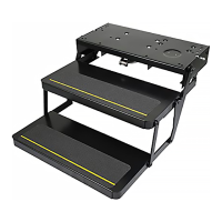
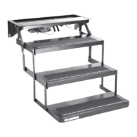
Reassembly and Installation of Motor Assembly
(Part #909501, #909502, #9095903, #9095904) to the Step Frame
 Loading...