Page 5
NOTE: For Van Step wiring kits order part #7541000
Installation: Wiring the Step
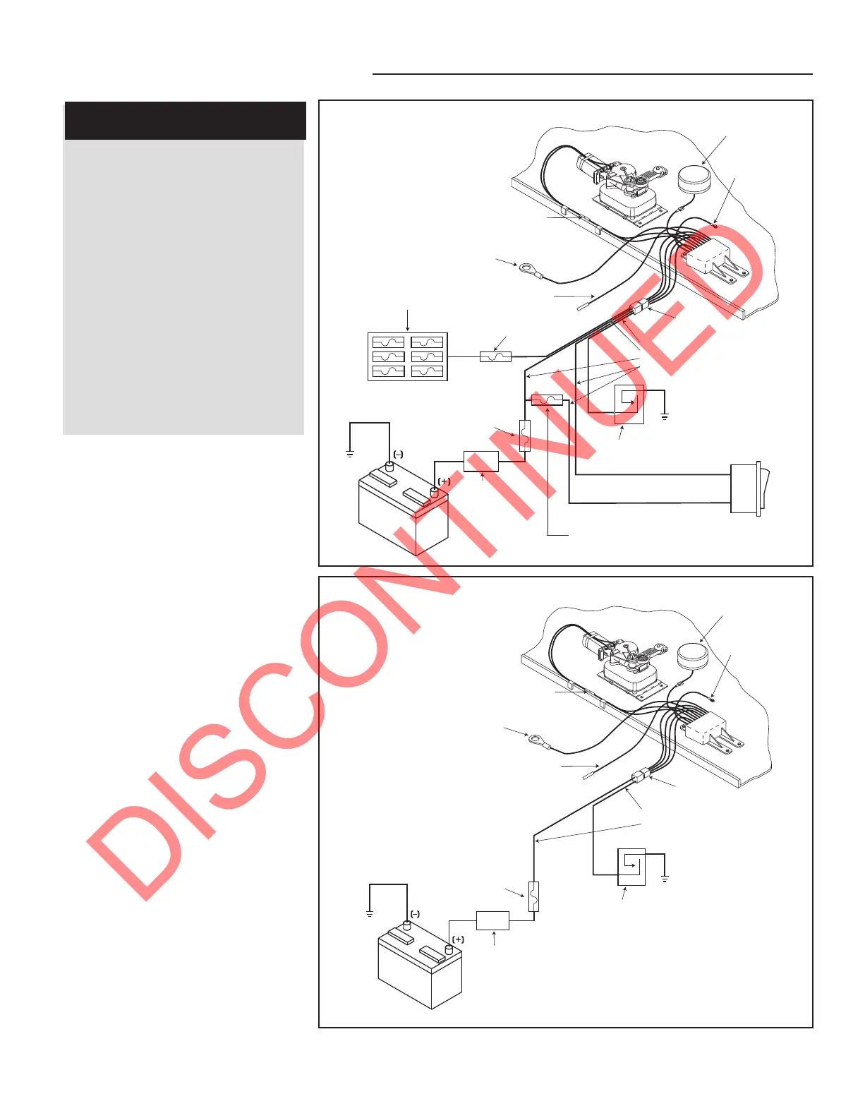
FIGURE 2: Wiring diagram
NOTE: For Van Step wiring kits order part #7540000
FIGURE 3: Wiring diagram for steps with
door switch only operation
Vehicle Wiring
Step Wiring
Motor
assembly
Understep light
(not available on
all step models)
12 AWG green
ground to step top
Control unit
(black)
Four-way
connector
16 AWG brown
12 AWG red
Chassis ground
Normally OPEN
magnetic door switch
20 amp fuse or
curcuit breaker required
Battery
disconnect
box/switch
IMPORTANT:
If the switch is
'OFF' the step
will not
operate.
Chassis
ground
12 volt DC
battery
Two-way
connector
12 AWG green ground wire
must be securely attached to
the chassis for step to operate
16 AWG purple
optional step light switch
Vehicle Wiring
Motor
assembly
Understep light
(not available on
all step models)
12 AWG green
ground to step top
Control unit
(black)
Four-way
connector
16 AWG brown
16 AWG yellow
12 AWG red
16 AWG white
Power
switch
Chassis ground
Normally OPEN
magnetic door switch
20 amp fuse or
curcuit breaker required
Battery
disconnect
box/switch
IMPORTANT:
If the switch is
'OFF' the step
will not
operate.
Chassis
ground
12 volt DC
battery
Fuse block
IMPORTANT:
The yellow wire must go to a
terminal marked IGN (ignition)
or to another terminal that is hot
when the ignition is turned on.
Two-way
connector
12 AWG green ground wire
must be securely attached to
the chassis for step to operate
16 AWG purple
optional step light switch
6 amp maximum fuse or
circuit breaker required
5 amp maximum fuse or
circuit breaker (not supplied)
Step Wiring
IMPORTANT
INSTALLER NOTES:
Kwikee recommends wiring the
step to the vehicle battery instead
of the “house” battery due to
potential interference from other
circuits.
Step controls require grounding
prior to installation of the positive
12 volt connections.
All Circuits noted as requiring
fuses must be fused. Fuses should
be located as close as practical to
the pwer source in order to
provide maximum protection to the
wiring circuits. Failure to provide
required fuses may void warranty.
NOTE: Prior to connecting any
wiring, disconnect the vehicle’s power
source at the battery.
1. Ground the control unit by
attaching the long green ground wire
from the control unit to the chassis (see
Figure 2 for all wiring details). For steps
with door switch only operations, follow
the wiring schematic illustrated in
Figure 3.
NOTE: A good ground connection is
required for proper step operation. To
insure a good ground connection
(metal-to-metal), scrape any paint
and/or undercoating from the ground
wire/vehicle chassis connection.
2. Determine the switch configuration
for the step that is being installed. The
step will be controlled by a normally
open magnetic door switch.
3. Once preliminary preparations are
finished for the door switch installation
(See Figure 4), connect the brown wire
lead from the vehicle half of the
four-way connector to one of the
terminals or wire leads from the door
switch. Use a minimum of 16 gauge
wire.
NOTE: Do not pull this lead tight.
Leave some slack to avoid damaging
the switch.
 Loading...