Page 6
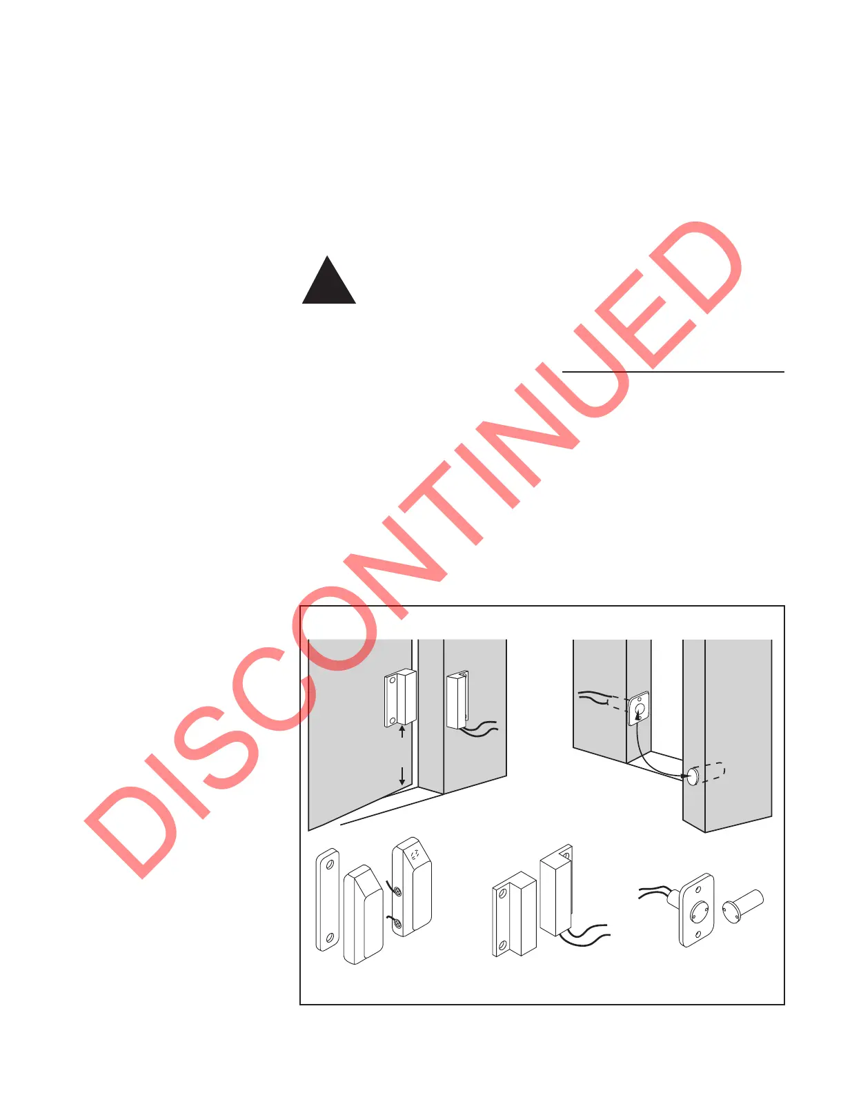
Door Switch Installation
FIGURE 4: Door switch installation
4. Connect a 16 gauge (minimum)
wire from the remaining door switch
terminal or wire lead to the chassis
ground. A good ground connection is
necessary to insure proper step
operation. Attach using a machine
screw, external or internal-tooth lock
washer, and a nut. Place the external or
internal-tooth lock washer between the
cable and the vehicle chassis. Scrape
any paint clear at this connection point
to insure a good ground.
5. Locate and cut a hole to mount the
power switch.
NOTE: There must be enough room
behind the switch to connect the wires
to the switch terminals. A rocker type
switch is available and may be used if
desired.
If the rocker switch is supplied by
Kwikee, the power switch may be
mounted as is by cutting a 1 9/16" x
7/8" hole for the switch to snap into.
NOTE: This hole must be very
accurate. The switch may also be
mounted using a bezel. Cut a 1 1/8" x 1
3/4" hole to mount the switch using the
bezel.
NOTE: Do not install the power switch
completely until all wiring to the switch
is in place.
6. Connect the white wire from the
four-way connector to one of the
terminals on the power switch. Use 16
gauge wire minimum.
7. Connect the yellow wire lead from
the four-way connector to the vehicle
fuse block. The yellow wire must go to
a terminal marked IGN (ignition) or to
another terminal that is hot only when
the ignition is turned on. A 6 amp
maximum fuse or circuit breaker is
required in the yellow wire. Use 16
gauge wire minimum.
8. Connect a 16 gauge minimum wire
from the other power switch terminal to
the red 12 gauge power wire. A 6 amp
maximum fuse or circuit breaker
attached as close as possible to the red
power wire is required in this line. The
wire must be connected to the red
power wire anywhere between the four-
way connector and the 20 amp fuse or
circuit breaker discussed in Step 9.
9. Connect the red power wire from
the four-way connector to the 12 volt
DC vehicle battery through a 20 amp
fuse or circuit breaker which is
designated for step use only.
WARNING: Do not
connect this wire to any
other circuit that runs
other functions. The circuit
must be dedicated to step use
only. Failure to do so will cause
severe damage to the control
unit, and will not be covered
under warranty. Use 12 gauge
wire minimum.
10. OPTIONAL: Step Light Switch
Connection- Attach the 16 gauge purple
wire from the control unit to the
switched lead of the porch light.
11. Wrap any exposed connection with
shrink wrap or electrical tape to protect
them from the weather. Mount the
power switch. Reconnect the battery.
!
NOTE: It is recommended that the
switch be installed on the latch side of
the door. However, hinge-side
installation is acceptable.
1. Some experimentation with the
switch position may be necessary to
achieve proper step operation. The step
should begin to extend when the door is
opened between one and four inches.
Position the magnetic switch in the door
jamb. Locate the magnet opposite the
switch.
2. Check for ample clearance in the
door frame for the door switch body. Do
not force the door switch into its
mounting position. Wiring to the
switch should come up through the
hollow door frame. After wiring is
completed, mount the switch to the door
jamb.
3. Install the magnet in the door,
opposite the switch. Vertical placement
of the magnet is critical to door switch
Door
Black
Large magnetic
reed switch
Black
Small magnetic
reed switch
Black
Round magnetic
switch
Door
Magnet
Switch
Switch
Upper
floor level
Door
Magnet
6"
minimum
 Loading...