Page 4
Introduction
Installation:
Mounting the Step and Retracting the Step
1. For easier installation, extend the
step by placing it upside-down on its
mounting surface.
WARNING: Making the
wire connections
detailed in this
procedure will cause the step to
quickly extend and retract.
Keep hands and fingers clear of
the step extension mechanism.
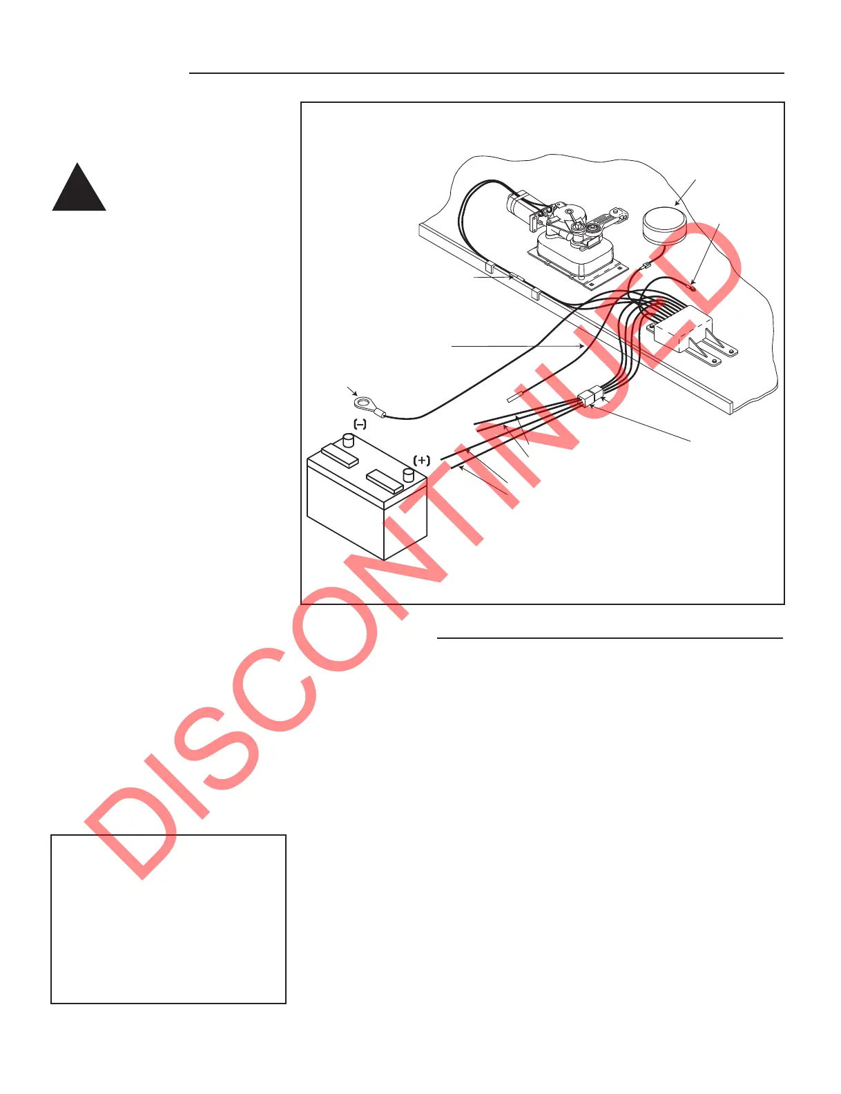
2. Connect the four-way connector
from the control unit with the four-way
connector/pigtail that has been included
with the step. Figure 1.
3. Ground the control unit by
attaching the long green ground wire
from the control unit to the negative (
_
)
terminal of a well charged 12 volt DC
automotive battery. The step will not
operate without a good ground
connection.
NOTE: If it is necessary to use jumpers
to connect the wire leads from the
pigtail to the battery, a minimum of 10
gauge wire (8 gauge for wiring runs
over 25 feet) is recommended for use
as jumper wire.
4. Attach the red wire from the pigtail
to the positive (+) terminal of the
battery. Keeping hands and fingers
clear from the step mechanism, touch
the white wire from the pigtail to the
positive (+) terminal to extend the step.
5. After the step has been extended,
disconnect the red and white pigtail
wires prior to disconnecting the green
ground wire from the battery. This will
keep the step in the extended position.
!
Motor
assembly
Understep light
(not available on
all step models)
12 AWG green
ground to step top
Control unit
(black)
Four-way connector
Optional four-way
connector/pigtail
(p/n 909306000)
12 AWG red (power supply)
16 AWG white (power switch)
16 AWG brown (door switch)
16 AWG yellow (ignition override)
12 volt DC
battery
Two-way
connector
12 AWG
green ground
16 AWG purple
optional step light switch
FIGURE 1: Extending the step for installation.
ATTENTION: For van steps equipped
for door switch only operation, connect
the green ground wire from the control
unit and the brown wire from the pigtail
to the negative (-) terminal of the
battery. Attach the red wire from the
pigtail to the positive (+) terminal of the
battery. Remove the brown wire from
the battery and the step will extend.
With 5/16-18 (minimum) bolts, lock
washers, and nuts, mount the step
using a minimum of four of the holes
located in the top of the step frame.
NOTE: Welding the electric step directly
to the chassis frame or mounting
bracket can distort the frame and
severely damage the control unit. This
damage will not be covered under the
warranty.
1. Ground the control unit by
attaching the long green ground wire
from the control unit to the negative (
_
)
terminal of a well charged 12 volt DC
automotive battery. The step will not
operate without a good ground
connection.
2. Attach the red and white pigtail
wires to the positive (+) terminal of the
battery.
3. Keeping hands and fingers clear
from the step mechanism, touch the
brown wire from the four-way
connector/pigtail to the negative (
_
)
terminal of the 12 volt battery. While
holding the brown wire to the battery,
remove the red and white wires from the
battery to keep the step retracted.
Note: For van step mounting
instructions refer to the Van Step
Mounting Bracket Instruction Sheet
included with the step.