Page 8
Step Test Procedures
!
Red
Red
Brown
4-way connector
(vehicle-side)
Ground wire: green ground wire
must be attached to vehicle
chassis; a good ground is needed
for proper step operation
Voltmeter should
read 12 volts DC
White
4-way connector
(vehicle-side)
4-way connector
(vehicle-side)
Ground wire: green ground wire
must be attached to vehicle
chassis; a good ground is needed
for proper step operation
Voltmeter should read
12 volts DC / power 'on'
0 volts DC / power 'off'
Voltmeter should read
12 volts DC when door
is closed
Voltmeter should read
0 volts DC when door
is open
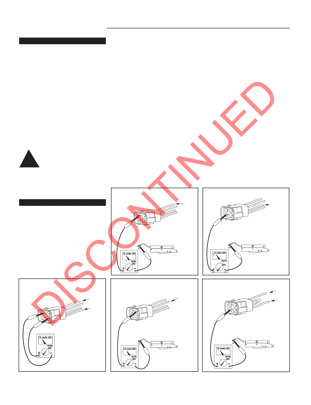
FIGURE 6: Check main
power source
FIGURE 8: Check door switch
FIGURE 7: Check power switch
FIGURE 10: Check connector
FIGURE 9: Check ignition
override
Yellow
4-way connector
(vehicle-side)
Ground wire: green ground wire
must be attached to vehicle
chassis; a good ground is needed
for proper step operation
Voltmeter should read
12 volts DC / ignition 'on'
0 volts DC / ignition 'off'
Red
Brown
4-way connector
(vehicle-side)
Ground wire: green ground wire
must be attached to vehicle
chassis; a good ground is needed
for proper step operation
Voltmeter should
read minimum of
12 volts DC
Testing the Motor
11. Disconnect the two-way connector
between the step motor and the control
unit.
Connect the motor’s red wire to the
positive (+) terminal of the battery and
touch the motor’s yellow wire to the
negative (
_
) terminal of the battery to
extend the step. To retract the step,
reverse the connections. If the step
extends and retracts during this test, the
condition of the step motor is good.
NOTE: On steps with control unit
#909507000 reverse the red and yellow
wire connections to perform the
aforementioned test.
WARNING: Do not leave
the wires connected
during this test once
the step has cycled either in or
out. Failure to remove the wires
from the battery will burn out
the motor voiding any warranty.
Testing the 4-way Connector
12. To check the main power source,
connect a voltmeter between the red
wire from the 4-way connector (vehicle
half) and the ground terminal at the end
of the control unit’s green ground wire
(see Figure 6). The reading should be
a minimum of 12 volts DC.
If the voltage reading is low, there may
be a loose or corroded connection at
the battery, a low charge level on the
battery itself, or a poor ground. If the
voltage reading is zero (0) volts, check
the step fuse/circuit breaker, all
connections, and the condition of the
wiring between the battery and the plug,
including the ground connection at the
chassis.
13. To check the power switch,
connect a voltmeter between the white
wire from the 4-way connector (vehicle
half) and the terminal at the end of the
control unit’s green ground wire (see
Figure 7). The reading should be a
minimum of 12 volts DC (the same as in
Step 12) when the switch is on, and
zero (0) volts DC when the switch is off.
If the voltmeter reads zero (0) volts
when the power switch is on, there is a
problem in the power switch circuit.
Check the 6 amp in-line fuse, the power
switch itself and the condition of the
circuit’s wiring and terminal connections.
14. To check the door switch, connect
a voltmeter between the red wire from
the 4-way connector (vehicle half) and
the brown in the same connector (see
Figure 8). The voltage should be a
minimum of 12 volts DC (the same as in
step 12) when the door is closed and
zero (0) volts when the door is open.
If the readings are incorrect, there is a
problem with the switch. Check the door
switch and the condition of the circuit's
wiring and terminal connections.
15. To check the ignition override
system, connect a voltmeter between
the yellow wire from the 4-way
connector (vehicle half) and the ground
terminal on the end of the control unit’s
green ground wire (see Figure 9). The
voltage reading should be
approximately 12 volts DC when the
ignition is on and zero (0) volts when
the ignition is off.
 Loading...