Page 14
Maintenance: Adjusting the Cam Stops
24, 25, 27, 32, 34, 35, 36, 38, and 40 Series Steps
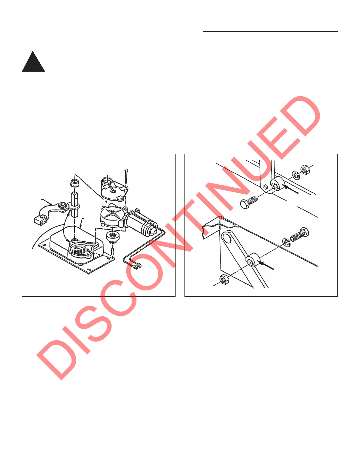
FIGURE 1
Linkage
Gear
Case
These
surfaces must
be in contact
for the step to be
fully extended.
Stop location and
assembly for 24, 25,
27, and 40 Series Steps
Stop location and assembly for 32, 34, 35, 36, and 38 Series Steps
This view shown with motor removed and parts exploded
for clarity only. These parts need not be disassembled to
adjust cam stops.
FIGURE 2
Push Step
securely against leg
Push Step
securely against leg
WARNING: When the
cam stops are out of
adjustment, the step
may feel loose or "mushy" when
stepped on. If the cam stops are
not properly adjusted the step
may not extend fully to the
locked-out position. Using a step
with loose or out-of-adjustment
cam stops may cause damage
to the motor assembly and/or
the drive linkage.
Kwikee steps are fitted with adjustable
cam stops on the step frame that help
lock the step in the "out" position,
creating a firm stepping platform and
relieving load-bearing stress on the
motor and drive linkage. The cam is
adjusted at the factory but due to the
rigors of shipping, installation, and
normal use the cam may fall out of
adjustment and need to be tightened.
The cam stops are located under the
step top on the 32, 36, and 38 Series
Steps, and on the bottom tread side rail
on the 24, 25, 27 and 40 Series Steps.
There is one stop on each side of the
step.
CAUTION: When working under
the step, be sure that the step
cannot be activated and that
nothing can get caught in the
step mechanism.
1. Loosen the stops so they move
freely and retract the step.
CAUTION: Be sure that nothing
can get caught in the step
mechanism.
2. Extend the step fully to its locked
extended position (see Figure 1). Be
sure that the motor assembly linkage
rests against the gear case as illustrated
in Figure 1. Repeat if needed until the
motor assembly locks in the extended
position.
3. Push the stops against the leg and
tighten securely (see Figure 2). Be sure
that both stops are tightened and that
they rest securely against the leg.
4. Retract and fully extend the step.
Check the motor assembly to be sure
that it is locked all the way out, and that
both stops are secure against the legs.
Repeat the above procedures if needed
to properly adjust the stops.
5. Push on the front edge of the step
tread. If the step seems loose, repeat
the above procedures. The stops may
not be properly adjusted so that they
rest tightly against the leg.
!