Do you have a question about the KYMCO X-Town 250 ABS and is the answer not in the manual?
Details the location of the Vehicle Identification Number (VIN) and engine serial number.
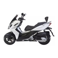
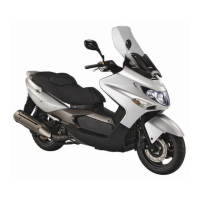
Provides detailed technical specifications for the X-Town 300 ABS and X-Town 250 models.
Lists important safety precautions and best practices for servicing the motorcycle.
Specifies torque values for various engine and frame components.
Lists specialized tools required for specific maintenance and repair procedures.
Illustrates lubrication points for the motorcycle frame and its components.
Diagrams showing the routing of cables and harnesses on the motorcycle.
Provides troubleshooting guides for common engine starting and performance issues.
General instructions and warnings related to exhaust muffler and frame cover service.
Specifies torque values for exhaust muffler mounting hardware.
Troubleshooting tips for common issues like noisy exhaust or lack of power.
Detailed procedure for removing and installing common fasteners.
Step-by-step guide for removing and installing various frame covers.
Procedure for removing the exhaust muffler and its related components.
Procedure for installing the exhaust muffler, including torque specifications.
General service information and warnings for inspection and adjustment tasks.
Key specifications for engine, tire, and other components for inspection.
Torque specifications for critical fasteners relevant to inspection and adjustment.
Identifies the specialized tool needed for specific inspection tasks.
Procedure for checking and adjusting throttle grip free play.
Instructions for checking engine oil level and performing oil changes.
Procedure for inspecting and refilling the coolant reserve tank.
Steps for replacing the air cleaner element and its maintenance interval.
Guidance on spark plug inspection, cleaning, and replacement.
Procedure for inspecting and adjusting valve clearance on a cold engine.
Method for testing cylinder compression and interpreting results.
Instructions for checking and changing final reduction gear oil.
Procedure for inspecting and replacing the drive belt.
Inspection and maintenance of the brake disk, pads, and fluid.
Method for checking clutch shoe wear and replacement criteria.
Inspection and adjustment of front and rear shock absorbers.
Guidance on checking chassis nuts and bolts for looseness.
Inspection of wheels and tires for damage and checking tire pressure.
Procedure for checking steering handlebar rotation and head bearing adjustment.
Inspection of the side stand and its ignition cut-off function.
Schematic diagram illustrating the lubrication system components.
General instructions and specifications for the lubrication system.
Specifications for engine oil capacity and oil pump rotor clearances.
Torque values for oil pump components and pressure switch.
Lists the specialized tool required for oil filter maintenance.
Troubleshooting guide for common lubrication system issues like low/high oil pressure.
Procedure for checking the oil pressure switch operation.
Steps for oil pump removal, disassembly, inspection, and assembly.
General instructions and warnings for engine removal and installation.
Engine oil and coolant capacities, and relevant torque values.
Specific torque values for engine hanger and mounting bolts.
Detailed procedure for removing the engine from the motorcycle.
Procedure for installing the engine, including post-installation checks.
Instructions for the removal and installation of the engine hanger.
Exploded view diagram of the cylinder head and valve components.
General instructions and specifications for cylinder head service.
Measurements for valve clearance, head warpage, camshaft height, and more.
Torque values for cylinder head nuts and bolts.
Identifies the valve spring compressor tool.
Common problems related to cylinder head operation and noises.
Procedure for removing the cylinder head cover.
Steps for removing the camshaft and related components.
Detailed procedure for removing the cylinder head from the engine.
Steps for disassembling the cylinder head, including valve components.
Procedure for inspecting valves, valve guides, and stem-to-guide clearance.
Steps for reinstalling the cylinder head onto the engine.
Exploded view diagram of the cylinder, piston, and related parts.
General instructions for servicing the cylinder and piston.
Measurements for cylinder I.D., warpage, piston O.D., and clearances.
Common issues related to compression, smoke, and noise involving cylinder/piston.
Procedure for removing the cylinder from the engine.
Steps for removing the piston from the cylinder.
Procedure for removing piston rings from the piston.
Methods for inspecting piston rings for movement and clearance.
Inspection of cylinder for warpage, wear, taper, and out-of-round.
Procedure for correctly installing piston rings into the piston grooves.
Steps for installing the piston and cylinder assembly onto the engine.
Exploded view diagram of the drive and driven pulleys and V-belt assembly.
General instructions and precautions for servicing pulleys and V-belt.
Specifications for clutch lining thickness, pulley I.D., and weight roller O.D.
Torque values for drive face and clutch nuts.
Lists specialized tools required for pulley and belt service.
Common issues with engine starting, lack of power, and stalling related to the drive system.
Procedure for removing the left crankcase cover.
Steps for removing the drive pulley face.
Procedure for removing the clutch outer, driven pulley, and V-belt.
Instructions for inspecting the drive belt for wear and damage.
Steps for removing the movable drive face assembly.
Procedure for disassembling the drive pulley components.
Inspection of weight rollers for wear or damage.
Inspection of clutch shoes for wear and clutch lining thickness.
Procedure for disassembling the clutch and driven pulley assembly.
Steps for replacing bearings in the driven pulley face.
Procedure for disassembling the clutch.
Steps for assembling the clutch components.
Procedure for assembling the clutch and driven pulley.
Steps for installing the drive and driven pulleys and related components.
Exploded view diagram of the final reduction gear components.
General instructions for servicing the final reduction system.
Specifications for the specified oil and oil capacity.
Torque values for transmission case cover and oil bolts.
Lists specialized tools for bearing and oil seal service.
Common issues related to engine starting, noise, and oil leaks in the final reduction.
Procedure for disassembling the final reduction unit.
Inspection of driveshaft, countershaft, and gears for wear or damage.
Procedure for replacing bearings within the transmission case.
Procedure for replacing the final gear shaft oil seal.
Steps for assembling the final reduction gears, shafts, and case.
Exploded view diagram of the A.C. generator and starter clutch components.
General instructions for servicing the A.C. generator and starter clutch.
Specifications for starter driven gear dimensions and system fluids.
Torque value for the flywheel nut.
Troubleshooting for starter motor issues and lack of power.
Procedure for removing the right crankcase cover.
Steps for removing the A.C. generator stator.
Procedure for removing the flywheel and starter clutch assembly.
Inspection of reduction gear, shaft, and sprag clutch operation.
Checking starter driven gear teeth and measuring its dimensions.
Procedure for installing the flywheel and related components.
Exploded view diagram of the crankcase and crankshaft components.
General instructions for crankcase separation and crankshaft service.
Specifications for crankshaft connecting rod end clearances.
Torque values for crankcase cover bolts and cam chain tensioner.
Common issues causing excessive engine noise in the crankcase/crankshaft.
Procedure for separating the crankcase halves.
Method for measuring crankshaft runout.
Steps for cleaning and assembling the crankcase.
Diagram illustrating the components of the cooling system.
General instructions and warnings for servicing the cooling system.
Specifications for radiator cap pressure, thermostat, and coolant capacity.
Torque values for water pump impeller and cover bolts.
Troubleshooting for engine overheating and coolant leaks.
Chart showing coolant concentration vs. specific gravity.
Procedure for testing the radiator cap and checking for leaks.
Inspection of the radiator for leaks and fin condition.
Steps for draining coolant and removing the radiator.
Procedure for installing the radiator and refilling coolant.
Inspection and removal/installation of the water pump and mechanical seal.
Procedure for removing the water pump shaft and bearings.
Instructions for replacing the water pump mechanical seal.
Procedure for installing the water pump shaft and bearings.
Steps for installing the water pump impeller and cover.
Procedure for removing, installing, and inspecting the thermosensor.
Steps for removing, inspecting, and installing the thermostat.
General instructions and precautions for servicing the fuel injection system.
Technical specifications for fuel injection system components.
Schematic diagram illustrating the fuel injection system components and connections.
Visual identification of key fuel injection system parts on the motorcycle.
Common problems and potential causes for fuel injection system issues.
Steps for performing self-diagnosis using the Check Engine Lamp (CELP).
Explains CELP codes and their meaning for Euro 3 models.
Procedure to reset the self-diagnosis system for Euro 3 models.
List of CELP failure codes, causes, and symptoms for Euro 3 models.
Procedure for resetting Throttle Position Sensor and Idle Speed Control.
Inspection, removal, and installation of the fuel pump.
Inspection and removal of the fuel cut-off relay.
Inspection, removal, and installation of the tilt switch.
Procedures for removing and installing the Electronic Control Unit (ECU).
Inspection, removal, installation, and cleaning of the fuel injector.
Steps for removing, installing, and inspecting the Water Temperature Sensor.
Procedure for removing, installing, and inspecting the Oxygen Sensor.
Inspection of throttle body, MAP, ISC, and TPS components.
Instructions for using the KYMCO Fi Diagnostic Tool.
Steps to check Diagnostic Trouble Codes (DTC) using the diagnostic tool.
Procedure for clearing Diagnostic Trouble Codes (DTC) from the system.
Guide on analyzing vehicle data, engine speed, and sensor readings via the diagnostic tool.
Basic checks and troubleshooting steps when the vehicle cannot be started.
Procedure for reading DTC from the speedometer or diagnosis tool.
General instructions and precautions for servicing steering and front brake systems.
Specifications for axle runout, brake disk thickness, and caliper dimensions.
Torque values for handlebar, steering stem, and brake components.
Lists specialized tools for steering stem and brake system maintenance.
Troubleshooting guides for steering issues, wheel wobbling, and brake performance.
Procedure for removing the handlebar and related controls.
Steps for installing the handlebar and tightening related fasteners.
Procedure for removing the front wheel and its components.
Method for measuring axle runout using a dial gauge.
Instructions for replacing brake fluid and bleeding air from the system.
Procedure for replacing front brake pads.
Inspection of the brake disc for thickness and warpage.
Procedure for removing the front shock absorber.
Steps for removing the steering stem and its components.
Procedure for installing the steering stem and adjusting.
Exploded view diagram of rear brake, fork, wheel, and shock absorber.
General instructions and precautions for rear brake/suspension service.
Specifications for rear wheel runout, brake disk, and master cylinder dimensions.
Torque values for exhaust muffler, rear axle, and shock absorber mounting.
Troubleshooting for rear wheel wobbling, brake performance, and suspension noise.
Procedure for removing the rear brake caliper.
Procedure for replacing front brake pads.
Steps for installing the brake caliper, fluid tube, and bleeding the system.
Procedure for removing the rear fork and related components.
Steps for removing the rear wheel and its components.
Procedure for removing the rear shock absorbers.
Instructions for adjusting the rear shock absorber spring preload.
Diagram showing the location of battery, regulator/rectifier, and ACG.
General instructions and warnings regarding battery and charging system service.
Specifications for battery capacity, voltage, and charging current.
Troubleshooting guide for power issues, low power, and charging system failure.
Procedure for removing the motorcycle battery.
Steps for installing the motorcycle battery correctly.
Method for measuring battery voltage using a multimeter.
Instructions and precautions for charging the motorcycle battery.
Procedure for testing charging system voltage with the engine running.
Inspection of wire harness connections for the regulator/rectifier.
Checking continuity and resistance of charging coil wires.
Procedure for removing and installing the regulator/rectifier.
Diagram showing the location of ignition system components.
Schematic diagram of the ignition system's electrical circuit.
General instructions and precautions for ignition system servicing.
Specifications for spark plug, ignition coils, and sensors.
Troubleshooting guides for no peak voltage and no spark issues.
Reference to spark plug inspection and adjustment on page 3-5.
Procedure for inspecting the ignition coil.
Method for testing ignition coil continuity and resistance.
Inspection of the A.C. generator and crank position sensor.
Procedure for inspecting the tilt switch voltage and continuity.
Procedure for removing and installing the tilt switch.
Diagram showing the location of the starter motor and relay.
Schematic diagram of the starting system's electrical circuit.
General instructions for starter motor removal and installation.
Specification for starter motor brush length.
Torque values for starter motor mounting and case screws.
Lists specialized tools for flywheel and starter motor service.
Troubleshooting for starter motor not turning and lack of power.
Procedure for removing the starter motor.
Steps for installing the starter motor and checking the O-ring.
Procedure for inspecting the starter relay continuity and operation.
Test procedure for the starter relay using a multimeter and battery.
Diagram showing the layout of electrical equipment on the motorcycle.
General instructions and warnings for servicing lights and switches.
Troubleshooting for lights not turning on and fuel gauge issues.
Specifications for fuses and various light bulbs.
Procedure for replacing the license plate light bulb.
Procedure for removing the headlight assembly.
Steps for installing the headlight bulb and assembly.
Procedure for replacing the front turn signal light bulb.
Procedure for accessing and replacing taillight bulbs.
Procedure for replacing the rear turn signal light bulb.
Inspection of the brake light switch continuity.
Procedure for inspecting the ignition switch continuity.
Inspection of the right handlebar switch continuity.
Inspection of the left handlebar switch continuity.
Inspection of the luggage box light switch continuity.
Procedure for removing the fuel pump.
Inspection of the fuel pump resistance and wiring.
Inspection of the side stand switch continuity.
Procedure for testing the horn operation.
Diagram showing components of the evaporative emission control system.
Explanation of the system's function in controlling fuel vapor emissions.
Common problems related to engine performance and idling in the emission system.
General instructions and tool requirements for emission system service.
Specifications for purge control valve vacuum pressure and canister capacity.
Diagram illustrating the piping for leakage testing of the emission system.
Procedure for removing the purge control valve.
Method for inspecting the purge control valve's vacuum holding capability.
Procedure for inspecting the purge control valve's flow rate.
Procedure for removing the charcoal canister.
Method for inspecting the charcoal canister for clogging and cracks.
Describes the function and behavior of the ABS indicator light on the instrument panel.
Explains the purpose and characteristics of the Anti-Lock Brake System (ABS).
Important notices regarding ABS operation, tire use, and limitations.
Identifies the location of key ABS components on the vehicle.
Procedure for removing and inspecting the front and rear wheel speed sensors.
Procedure for removing and installing the ABS ECU and Hydraulic Unit.
Instructions for using the KYMCO Fi Diagnostic Tool for ABS system checks.
Steps to check Diagnostic Trouble Codes (DTC) using the diagnostic tool.
Procedure for clearing Diagnostic Trouble Codes (DTC) from the ABS system.
Guide on analyzing ABS system data, sensor readings, and vehicle speed.
A list of Bosch ABS8m Diagnostic Trouble Codes (DTC) with descriptions.
| Displacement | 249.1 cc |
|---|---|
| Fuel System | Electronic Fuel Injection |
| Starter | Electric |
| Transmission | CVT |
| Front Suspension | Telescopic fork |
| Rear Suspension | Dual Shocks |
| Rear Tire | 150/70-13 |
| Fuel Capacity | 12.5 liters |
| Wheelbase | 1545 mm |
| Front Brake | Disc, ABS |
| Rear Brake | Disc, ABS |
| Front Tire | 120/70 |