© 2019 Kymeta Corporation and its affiliates. 2 08 March 2019
Kymeta™ u7 terminal usermanual
2 Indoor unit
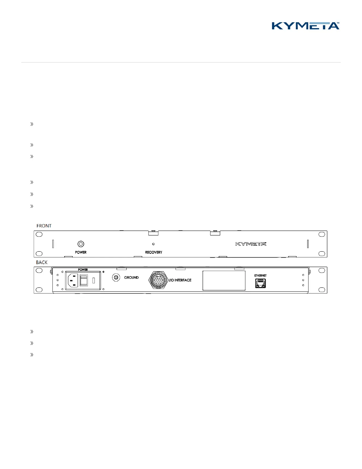
2.1 I/O box
The I/O box is a vital component of the Kymeta u7 antenna. It is designed to operate indoors above the modem in the
same rack.
The I/O box performs the following key tasks in the operation of the antenna:
Connects the antenna (and the BUC in the u7 terminal) to an AC power supply via a standard IEC C13 plug
connection from the I/O box to your local power supply.
Connects the u7 antenna to a switch or router with an Ethernet interface.
Provides a physical remote connection to the u7 antenna for recovery.
The I/O box has a user interface comprised of the following elements:
A Power switch on the back
A Status light on the front
A Recovery button on the front
The I/O box is connected to the u7 antenna through a single ODU interface cable.
The I/O box contains the following ports:
I/O interface
Ethernet
Power
2.1.1 I/O interface
The ODU interface cable uses an 18-pin locking connector.
2.1.2 Ethernet
The Ethernet port is the primary M&C port and is a standard 10/100/1000 Ethernet. It supports multiple protocols for a
web server (GUI), ACU-Modem Interface (OpenAMIP™), and an M2M (machine-to-machine) RESTful API. Installation
engineers can make multiple connections through use of an external switch.
 Loading...