© 2020 Kymeta Corporation. All rights reserved. 30 08 December 2020
700-00121-000 revD Kymeta u8 products installation and user guide
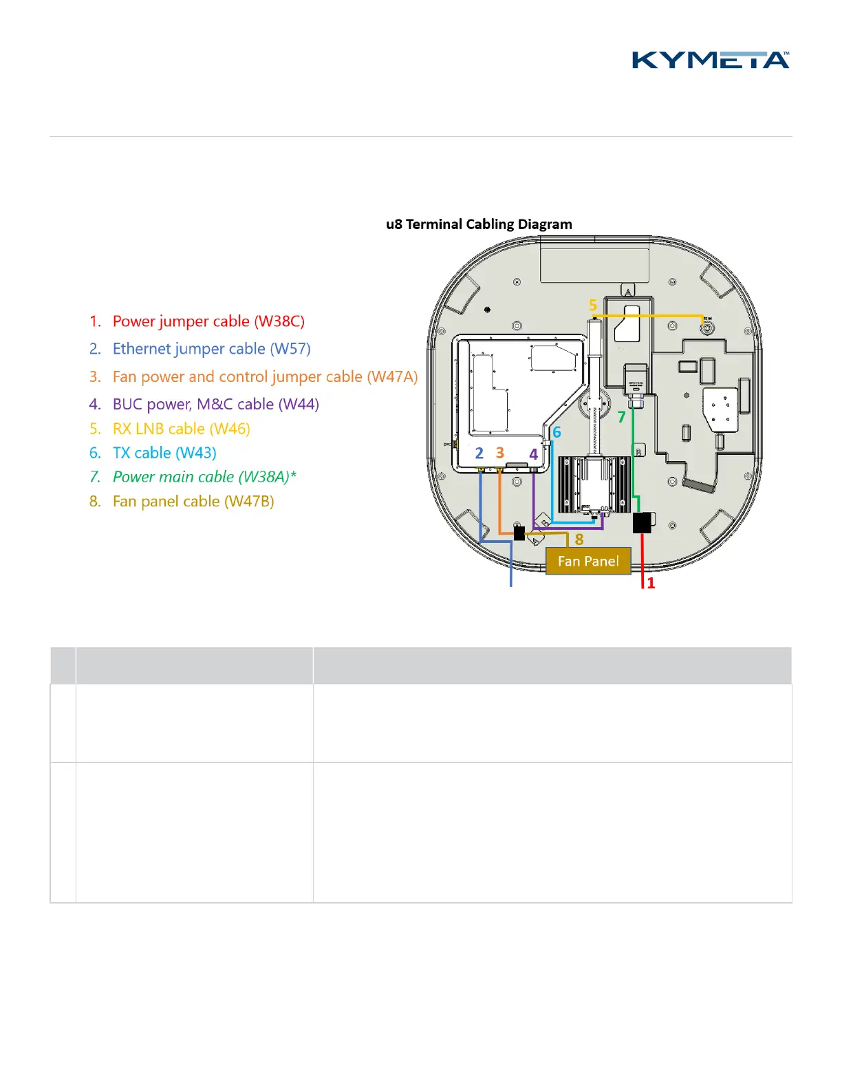
Appendix A. Kymeta u8 terminal cabling diagram
Six field-replaceable external cables reside under the u8 terminal shroud. The power jumper cable and Ethernet jumper
cable move connection interfaces outside the shroud to improve installation experience.
*The power main cable (W38A) is not replaceable.
# Cable name and product code Cable description
1
Power jumper cable (W38C)
(U8ACC-00017-0)
This cable can be connected to the u8 vehicle power kit (U8ACC-00001-0).
If you want to use the AC-to-DC power kit (U8ACC-00002-0), replace the
power jumper cable with the cable provided with the kit.
2 Ethernet jumper cable (W57)
(U8ACC-00018-0)
This cable connects the communication module to port 1 on the modem.
The Ethernet port is for a standard 10/100/1000 network and is the
primary monitor and control (M&C) port. It supports multiple protocols
for a web server (GUI), ACU-modem Interface (OpenAMIP), and an M2M
(machine-to-machine) RESTful API. Installation engineers can make
multiple connections with an external switch.