2NM/2NX/2NY/2NZ/2P0/2P6
1-5-69
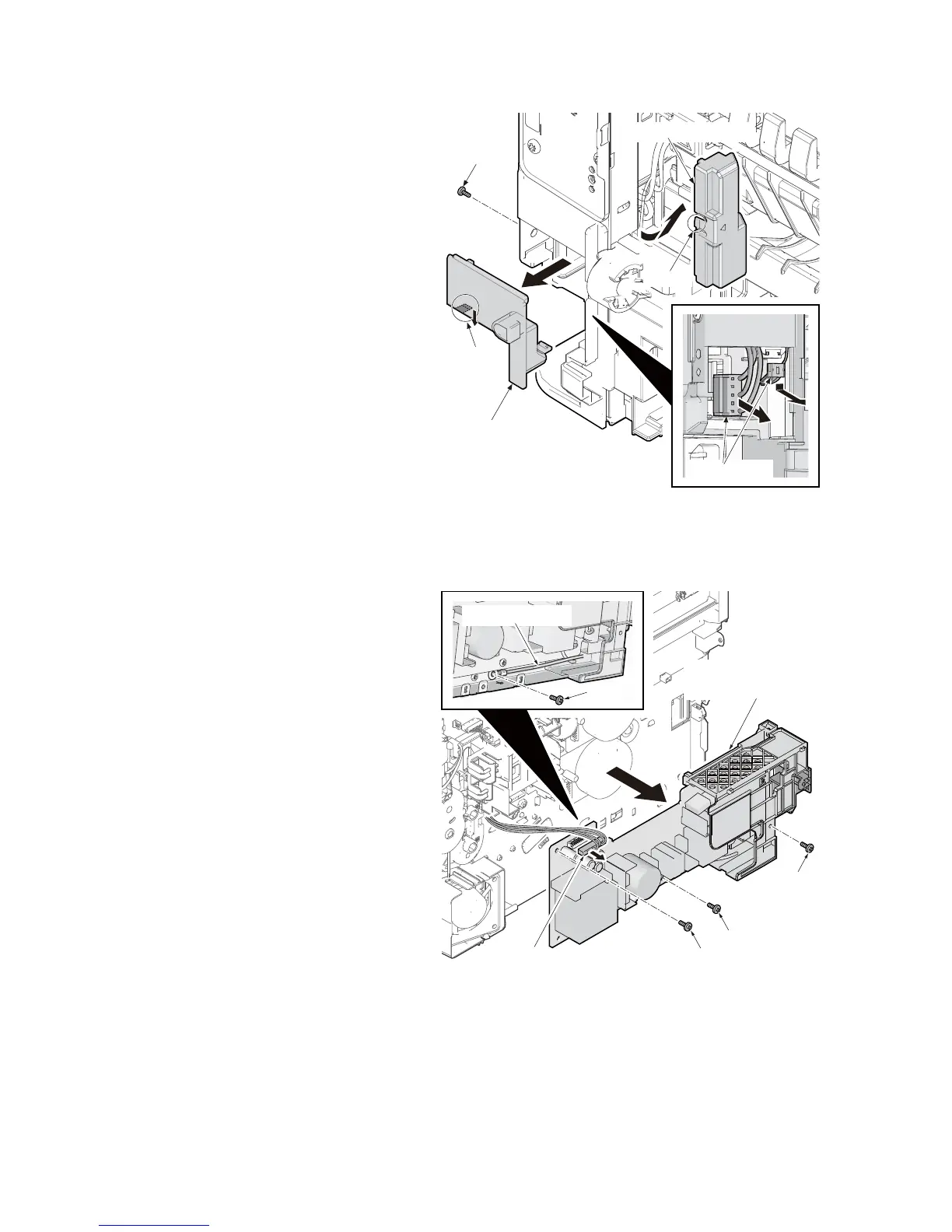
24. Remove the connector cover B by
releasing the hook.
25. Remove the screw of connector cover
C.
26. Remove the connector cover C by
releasing the hook.
27. Pull two connectors out.
Figure 1-5-117
28. Remove the connector from the power
source PWB assembly.
29. Remove the grounding wire by remov-
ing the screw.
30. Remove three screws and then remove
the power source PWB assembly.
31. Check or replace the power source
PWB and refit all the removed parts.
Figure 1-5-118
Screw
Connector cover C
Hook
Connectors
Hook
Connector cover B
Power source PWB
assembly
Screw
Screw
Screw
Screw
Grounding wire
Connector
 Loading...