Do you have a question about the Kyocera ECOSYS M6526cidn and is the answer not in the manual?
Explains the meaning and usage of various symbols for safety warnings and precautions.
Details the technical specifications of the machine, including type, printing method, paper handling, and speed.
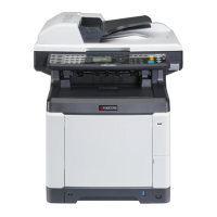
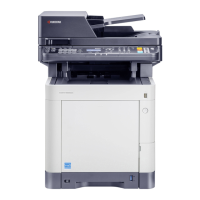
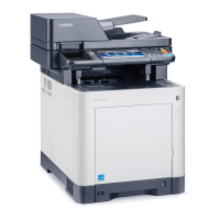
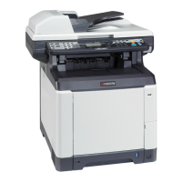
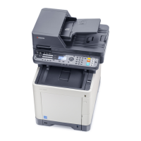
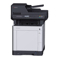
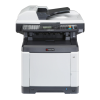
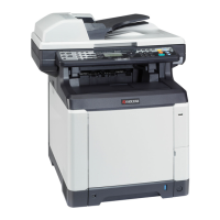
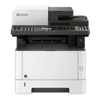
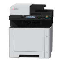
Identifies and labels the various external parts of the machine's front and rear sides.
Illustrates the internal mechanical construction and component layout of the machine.
Specifies the required environmental conditions for machine installation, including temperature, humidity, and power supply.
Provides a step-by-step guide for safely unpacking the machine and its components from the shipping box.
Details the procedure for installing optional expansion memory modules into the machine.
Outlines the steps for installing an optional SD card into the machine for storage or firmware updates.
Explains how to access and execute maintenance functions within the machine's operation menu.
Describes how to access and utilize the machine's service mode for diagnostic and maintenance tasks.
Lists all available maintenance modes with their item numbers, content, and initial settings.
Provides detailed descriptions, purposes, and methods for executing specific maintenance mode items.
Explains how the machine detects paper misfeeds and how to interpret paper jam locations.
Details the machine's self-diagnostic capabilities and provides a list of self-diagnostic codes and their meanings.
Identifies common image quality issues and provides visual examples and potential causes.
Lists electrical issues, their causes, and recommended procedures for troubleshooting and repair.
Covers common mechanical problems, their causes, and corrective measures for parts like rollers and clutches.
Lists error codes related to scanning functions such as SMB, FTP, and E-mail, with troubleshooting steps.
Provides a classification system for error codes and lists general classifications for various communication errors.
Outlines essential safety precautions and handling guidelines before starting disassembly or assembly procedures.
Details the process of removing and refitting the machine's various outer covers for access to internal components.
Explains how to detach and refit components within the paper feed sections, including rollers and trays.
Provides instructions for removing and reinstalling the developing units, which contain toner cartridges.
Details the procedure for detaching and refitting the drum units, crucial for image formation.
Describes how to remove and reinstall the intermediate transfer unit and transfer roller.
Outlines the steps for detaching and refitting the fuser unit, responsible for fixing toner onto paper.
Covers the detachment and refitting of various Printed Wiring Boards (PWBs) within the machine.
Explains the procedures for removing and reinstalling drive units like motors and clutches.
Details the disassembly and reassembly of optical components, including scanner units.
Provides instructions for detaching and refitting the document processor and its related parts.
Covers the removal and refitting of miscellaneous components not categorized elsewhere.
Guides users through the process of upgrading the machine's firmware using a USB memory device.
Provides important notes regarding the replacement of the engine PWB, specifically about the EEPROM.
Describes the mechanical components responsible for feeding and conveying paper from various sources.
Details the components of the drum section, including the drum, charger roller, and cleaning unit.
Explains the structure of the developing unit, including rollers, blades, and toner sensors.
Covers the image scanner and laser scanner sections, detailing their components and optical paths.
Describes the intermediate transfer unit and secondary transfer roller mechanisms.
Explains the fuser unit's components, including heat and press rollers, and their function in fixing toner.
Details the mechanical path for paper ejection and feed shifting after the fuser section.
Describes the paper path used for duplex printing operations.
Explains the components and operation of the document processor for scanning originals.
Provides a visual overview and description of the main PWBs within the machine's electrical system.
Identifies and describes the function of various switches and sensors used in the machine's operation.
Lists and describes the purpose of the different motors used to drive various mechanical sections of the machine.
Categorizes and describes other miscellaneous components like clutches and lamps.
Details the electrical components and sensors within the document processor.
Details the connectors and signals of the power source PWB, responsible for power distribution.
Provides the silk-screen diagram and pin assignments for the Engine PWB.
Shows the silk-screen diagram of the Main PWB, illustrating connector locations.
Displays the silk-screen diagram and pin assignments for the Drum relay PWB.
Shows the silk-screen diagram and pin assignments for the DP drive PWB.
Lists maintenance kits with their part numbers and alternative part numbers for service.
Illustrates repetitive defect intervals for various rollers, indicating potential wear patterns.
Explains how to use FRPO commands for reprogramming firmware parameters and lists available settings.
Provides alternative commands for maintenance modes, including print start timing and scanner magnification adjustments.
Displays the overall wiring diagram of the machine's electrical system, showing interconnections between PWBs.
| Category | All in One Printer |
|---|---|
| Print Technology | Laser |
| Monthly Duty Cycle | Up to 50, 000 pages |
| Copy Resolution | 600 x 600 dpi |
| Standard Paper Capacity | 250 sheets |
| Duplex Printing | Yes |
| Operating System Compatibility | Windows, Mac OS, Linux |
| Type | Laser |
| Functionality | Copier, Printer, Scanner, Fax |
| Scan Resolution | 600 x 600 dpi |
| Fax Resolution | 300 x 300 dpi |
| Connectivity | USB, Ethernet |
| Weight | 26 kg |