2T6/2T7/2T8/2T9
1-2-12
1-2-3 Installing the optional equipment
(1) Expansion memory
Procedure
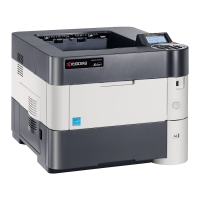
1. Remove the inlet cover.
2. Remove the slot cover.
3. Unplug the power cable.
Caution: Do not insert or remove main
PWB assembly while machine power is
on.
Doing so may cause damage to the
machine and the main PWB.
Figure 1-2-21
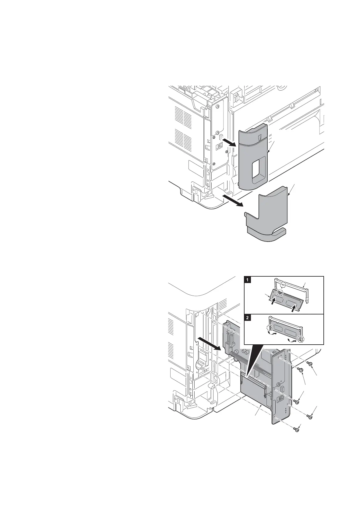
4. Remove five screws and then remove
the main PWB assembly.
5. Aligning the cutouts of the memory
module with the matching keys of the
socket, carefully plug the memory mod-
ule into the memory socket until it clicks
in place.
6. Then, push down the memory module
to secure.
7. Refit the main PWB assembly and the
screws.
8. Refit the covers.
9. Plug the printer into a power outlet.
10. Print a status page to check the mem-
ory expansion. (See page 1-3-2)
If memory expansion has been properly
performed, information on the installed
memory is printed with the total memory
capacity has been increased.
Standard memory capacity 256 MB.
Figure 1-2-22
Slot cover
Inlet cover
Expansion
memory
Memory socket
Screw
Screw
Screw
Screw
Main PWB
Assembly
 Loading...