In the event of a fault, the Fault loop impedance should be low enough
(and the Prospective Fault current higher enough) in order to have the
automatic disconnection of supply by the installed protection device within
prescribed time interval.
Every circuit must be tested to make sure that the fault loop impedance
does not exceed that specified for the over current protection device
concerned.
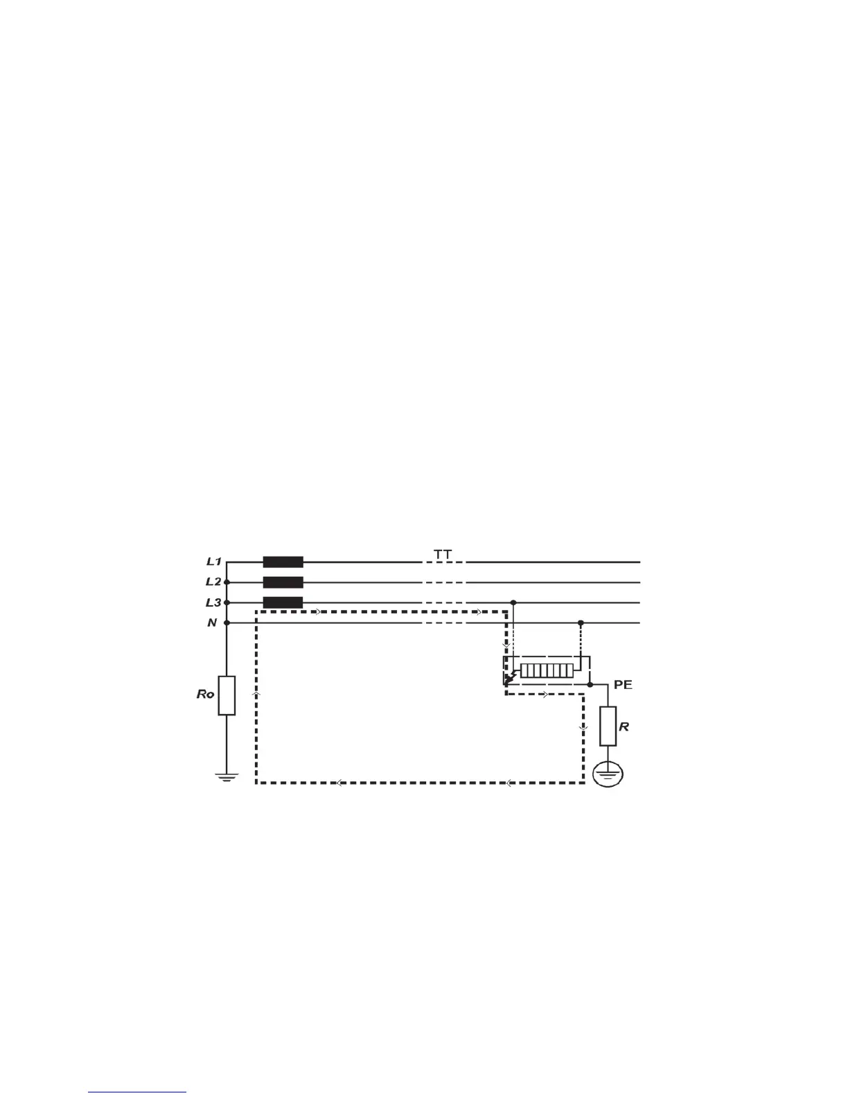
For TT system the Fault loop impedance is the sum of the following partial
impedances:
◦ Impedance of power transformer's secondary.
◦ Phase conductor resistance from power transformer to fault location.
◦ Protection conductor resistance from fault location to local earth
system.
◦ Resistance of local earth system R.
◦ Resistance of power transformer's earth system Ro.
The figure below shows in marked line the Fault loop impedance for TT
system.
Fig.6
For TN system the Fault loop impedance is the sum of the following
partial impedances:
◦ Impedance of power transformer's secondary
◦ Phase conductor resistance from power transformer to fault location
◦
Protection conductor resistance from fault location to power transformer