Fig.7
According to the international Standard IEC 60364 for TT system the
following condition shall be fulfilled for each circuit:
RA
<
50/Ia
Where:
◦ RA is the sum of the resistances of the local earth system R and
protection conductor connecting it to the exposed conductive part.
◦ 50 is the max contact voltage limit (it could be 25V in particular cases)
◦ I a is the current causing the automatic disconnection of the protective
device within 5 s.
When the protection device is a residual current device (RCD), Ia is the rated
residual operating current I
⊿
n.
For instance in a TT system protected by a RCD the max RA values are:
Note:
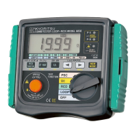
● The loop tester models 4118A measure the fault loop impedance
that is a value normally a little bit higher of RA.
But, if the electrical installation is protected considering the loop
impedance value, also the RA formula will be fulfilled.
Rated residual operating current I ⊿ n.
RA (at 50V)
10
5000
2500
30
1667
833
100
500
250
300
167
83
500
100
50
1000
50
25
mA
Ω
Ω
RA (at 25V)
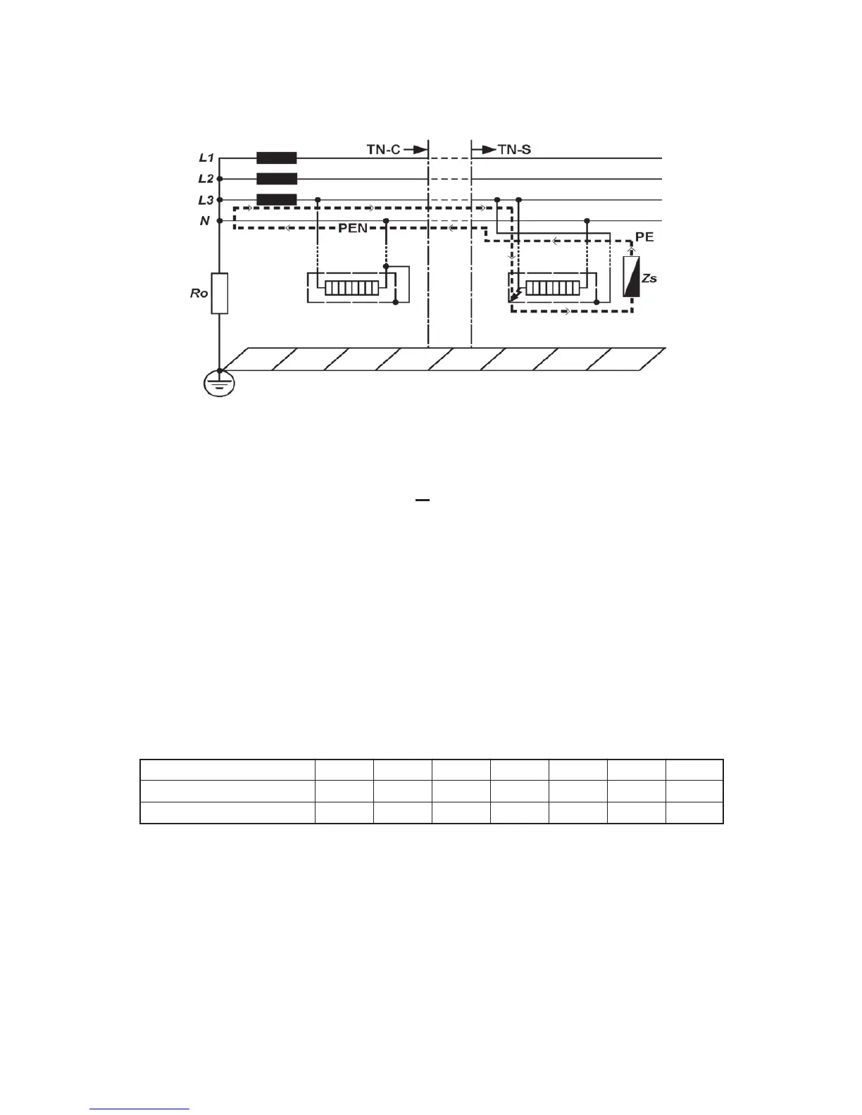
The figure below shows in marked line the Fault loop impedance for TN
system.