A1
A2
A4
A3
w
6
P6
5 P5
4
P4
7 P7
8 P8
2
P2
1 P1
3 P3
B3
E
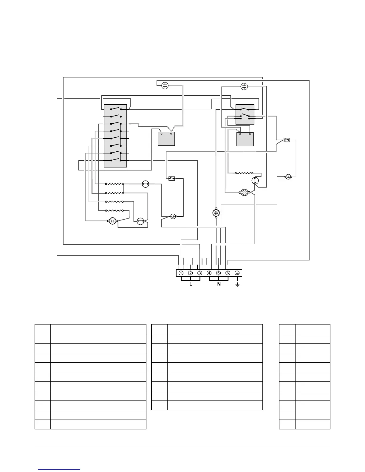
Legend
The connections shown in the circuit diagram are for single-phase. The ratings are for 230 V 50 Hz.
Code Description
A1 Left-hand oven light switch
A2 Left-hand oven light
A3 Right-hand oven light switch
A4 Right-hand oven light
B2 Left-hand oven thermostat
B3 Left-hand multi-function oven switch
B4 Left-hand oven top element
B5 Left-hand oven browning element
B6 Left-hand fan element
B7 Left-hand oven base element
Code Description
B8 Left-hand oven fan
C Cooling fan
D1 Right-hand oven front switch
D2 Right-hand oven thermostat
D3 Right-hand oven fan element
D4 Right-hand oven fan
E Thermal cut-out
F Neons
Code Colour
b Blue
br Brown
bk Black
or Orange
r Red
v Violet
w White
y Yellow
g/y Green / Yellow
gr Grey