Do you have a question about the Lab.gruppen fP Series FP 6400 and is the answer not in the manual?
Explains warning symbols like lightning and exclamation points.
Advises against exposing apparatus to rain or moisture.
Advises not to remove screws and to refer servicing to qualified personnel.
Lists crucial safety guidelines for amplifier operation and handling.
Outlines user's role in safe operation and preventing damage.
Warns about amplifier power potentially damaging loudspeakers.
Warns about hazardous output voltages and touching exposed speaker wiring.
Discusses compliance with EMC/FCC rules and potential interference.
Instructions for carefully unpacking the amplifier and checking for damage.
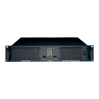
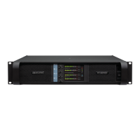
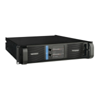
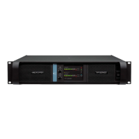
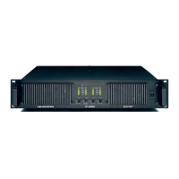
Identifies and describes the components on the amplifier's front panel.
Identifies and describes the components on the amplifier's rear panel.
Explains how the rear panel DIP-switch adjusts input sensitivity.
Details the layout and function of the rear panel DIP switches.
Defines sensitivity and how it relates to input voltage and output power.
Describes the function of the Link switch for changing operation modes.
Details different amplifier operation modes like Stereo, Tandem, and Bridge Mono.
Discusses optional modifications to the DIP switch bay.
Explains independent channel operation for stereo and bi-amping.
Provides specific instructions for bench testing the amplifier.
Describes linking both channels for the same input signal.
Explains how to combine both channels for a single load.
Highlights benefits of bridged mono mode, like increased power.
Explains MLS switch for matching impedance and optimizing power.
Provides guidance on selecting optimal MLS settings for applications.
Explains the technical background of MLS technology.
Discusses issues with conventional amplifiers driving low impedances.
Presents the "Constant Power Converter" solution for low impedance loads.
Guidance on rack mounting the amplifier, including spacing and supports.
Explains the forced air cooling system and airflow requirements.
Instructions on connecting the correct AC mains voltage and its implications.
National deviation concerning mains fuse requirements for Denmark.
National deviation concerning mains connector type for Switzerland.
Details grounding procedures, avoiding ground lift, and AC mains filter requirements.
Explains how to determine amplifier power and current consumption.
Provides examples and charts for calculating heat power and efficiency.
Describes how to connect input signals using XLR and 1/4" jacks.
Details wiring for balanced XLR and 1/4" TRS inputs.
Explains connecting unbalanced sources and minimizing hum.
Instructions for connecting speakers using Neutrik NL4FC Speakon connectors.
Lists essential precautions before powering up or operating the amplifier.
Describes the amplifier's soft-start sequence and initial operational indicators.
Explains the function of front panel attenuators for signal level adjustment.
Describes the front panel LEDs (yellow for protection, green for signal/power).
Explains the clip limiter's role in preventing speaker damage from clipped signals.
Details how thermal protection mutes the signal to prevent overheating.
Describes VHF protection muting signals above 12kHz to prevent output damage.
Explains the protection against short circuits on the outputs.
Describes the AFS limiter for preventing mains breaker trips during high current draws.
Explains protection against over or under AC mains voltage.
Explains the green AC LED indicating mains power presence.
Details DC protection mechanisms for the output channels.
Lists common faults and checks for diagnosing amplifier issues.
| Number of Channels | 2 |
|---|---|
| Total Harmonic Distortion (THD) | < 0.1% |
| Voltage Gain | 32 dB |
| Frequency Response | 20 Hz - 20 kHz |
| Damping Factor | > 500 |
| Input Sensitivity | 1.4 V |
| Input Impedance | 20 kΩ |
| Dimensions (H x W x D) | 3.5 x 19 x 15.5 in |