Architects’ and Engineers’ Specification
FP+ Series: Dedicated Touring Amplifiers
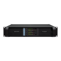
FP 10000Q
Item no. AES-FP10000Q_V2
Lab.gruppen ab • Sweden
internationaL contact • info@Labgruppen.com | uS contact • infouS@tceLectronic.com
www.labgruppen.com
Overview: Channel Modes and Network
The power amplifier shall provide four discrete channels of amplifica-
tion. Rear-panel switches shall enable bridging of adjacent channels
to allow reconfiguration as a 2- or 3-channel amplifier, with increased
power output available through the bridged channels. The amplifier
shall employ a proprietary tracking Class D output circuit topology.
The amplifier shall be equipped with sensing and communication
circuits to allow comprehensive remote control and monitoring func-
tions via a separate network bridge. The proprietary control and
monitoring network shall use Cat-5 cable for interconnection, and
shall allow control and monitoring directly from the network bridge’s
front-panel or, via the bridge, from an external PC running proprietary
software.
Power Output and Performance
Maximum total output of all four channels shall be 10000 watts. In
discrete four-channel mode, each amplifier channel shall deliver max-
imum continuous output power as follows: 660 watts into 16 ohms,
1300 watts into 8 ohms; 3100 watts into 4 ohms; or 2500 watts into
2 ohms. Maximum output voltage per channel shall be 150 Vrms;
maximum output current per channel shall be 38 Arms. In bridged
mode, each bridged channel shall deliver maximum continuous out-
put power as follows: 2600 watts into 16 ohms; 4200 watts into 8
ohms; or 5000 watts into 4 ohms.
Default amplifier gain shall be 35 dB, with rear-panel adjustment
from 23 to 44 dB in 3 dB increments, selectable for each channel. For
bridged channels, the amplifier shall automatically compensate -6 dB
gain internally to maintain operation of all channels at selected gain.
The amplifier shall exhibit the following performance parameters
with gain set at 35 dB and VPL (Voltage Peak Limiter) at 150 V:
Frequency response shall be 6.8 Hz to 34 kHz, +0/-3 dB at 1 watt
into an 8 ohm load; channel separation shall be greater than 70 dB;
and signal-to-noise ratio shall be greater than 112 dBA. THD at 1
watt, 20 Hz – 20 kHz, shall be less than 0.1%; THD at 1 kHz shall be
no more than 0.05% at 1 dB below clipping.
A VPL shall limit peak output as determined by rear-panel switches.
In discrete four channel mode, peak voltage shall be selectable in
eights steps across a range of 150 V to 38 V. In bridged mode, peak
voltage shall be selectable in eight steps from 300 V to 76 V. The
voltage limiter mode shall be selectable for either Hard or Soft limit-
ing characteristics.
Connectors, Controls, and Indicators
The following connectors and controls shall be on the REAR-PANEL
of the amplifier. The four input connectors shall be electronically ba-
lanced XLR-F. The four output connectors shall be either bind-
ing post or Neutrik Speakon. A group of seven DIP-switches shall
determine the following: amplifier gain (23 dB to 44 dB in 3 dB incre-
ments); option active; fan masked; and bridged mode selection for
channel pairs. A group of sixteen DIP-switches shall determine VPL
values for each channel (selectable in eight steps), and Hard or Soft
limiting characteristic. Two Ethercon-housed RJ45 connectors shall
be provided for input and output of the control/monitoring network
signals. An LED adjacent to the RJ45 connectors shall indicate active
or inactive status of the network.
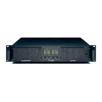
The following indicators and controls shall be on the FRONT-PANEL
of the amplifier. Four level control potentiometers shall be detented
and provide attenuation from 0 dB to infinity in 21 steps. Individual
switches shall be provided for power on/off and remote power on/off
enabling. Front-panel LED indicators shall be provided to show status
of power on/off (green), network connection (blue), and PAL (Power
Average Limiter) (red). Additional LED indicators shall be provided
to show the status of the following for each channel: signal present
and high-impedance warning (green/red), signal present from -20 dB
to -4 dB (4x green), VPL clipping (red), CPL (Current Peak Limiter)
active (orange), VHF (Very High Frequency) warning (yellow), high
temperature warning (yellow flashing), and high temperature fault
with output muted (yellow constant), and Mute (red).
Power Supply, Protection, and Cooling
The power supply shall be a regulated switch mode type. The ampli-
fier shall operate from AC line sources of either 230 V nominal or 115
V nominal, with operating ranges of 130 – 265 V and 65 – 135 V at
line frequencies of 50 Hz or 60 Hz. Minimum power-up voltages are
171 V (230 V nominal) and 85 V (115 V nominal). A soft start circuit
shall limit current inrush at power-up to 5 A. The amplifier shall be
equipped with a PAL circuit to prevent excessive current draw. The
amplifier shall be cooled by two temperature-controlled, variable-
speed fans, with air flow from front-to-back. An adaptive fan on/off
function shall be dependent on presence of an output signal.
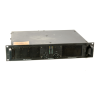
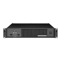
Physical
The amplifier shall be 483 mm (19 in.) wide, 88 mm (3.5 in / 2 U)
high, and 396 mm (15.6 in.) deep. The weight shall be 12 kg (26.4
lbs). The cabinet shall be black painted steel with a black painted
steel and aluminum front-panel.
The amplifier shall be approved for use as specified by CE,
ANSI/UL, ETL and the FCC. The amplifier shall be the Lab.gruppen
FP 10000Q.