6
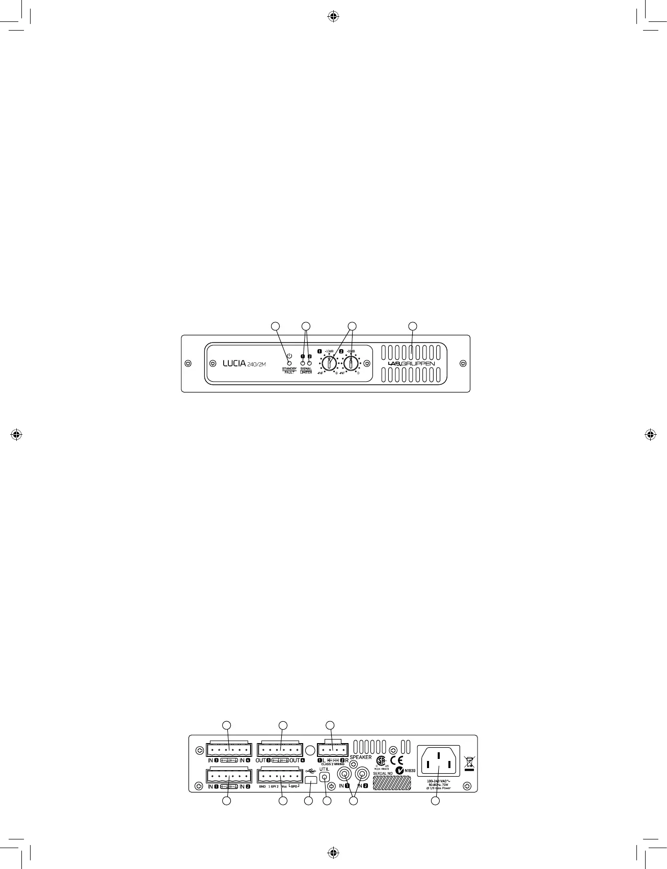
Front panel (all LUCIA models)
The front panel presents the following amplifier status indicators:
1 Standby/On LED indicator – A three-color LED illuminates amber
when amplifier is in standby power mode and illuminates green when
the amplifier is on. When the amplifier enters Protection mode, the LED
flashes red and the speaker outputs are muted. For more information on
Protection mode, please refer to the full Operation Manual.
2 Signal present/limit/clip indicators – A three-color LED illuminates
to provide channel status information as follows:
Green – Signal is present at the input and the channel is operating
normally.
Amber – Limiting is active on the channel. Limiting is engaged when:
• The channel reaches the voltage limit as determined by the
automatic Voltage Peak Limiter (VPL) setting
• Maximum current output is reached
• Mains voltage cannot maintain rail voltage
Red – Channel is clipping either at the input or in DSP.
3 Signal attenuators – A signal attenuator is provided for input
channels 1 and 2. Attenuators are adjustable over a range of minus infinity
to 0 dB.
Note: In LUCIA constant voltage mono models (60/1-70, 120/1-70 and
240/1-70), the attenuators provide an input select and mixing function by
setting the level from each input that goes to the single output channel.
4 Airow input – Make certain this input is not blocked or covered.
Rear panel: Two output low impedance models
(LUCIA 60/2, 120/2, 240/2, 60/2M, 120/2M, 240/2M)
1 Balanced audio inputs (1 & 2) – Connect balanced inputs using
3-pole Euroblock connectors. Correct polarity (+, -) and ground
terminations are shown on the rear panel.
2 Unbalanced audio inputs (1 & 2) – Connect unbalanced inputs (e.g.
local video screen output, CD player) to the RCA (phono) inputs. Note:
Balanced and unbalanced inputs are in parallel; only one pair of inputs
should be connected at one time.
3 Speaker outputs – Connect loudspeakers with nominal impedance
of 2, 4, 8 or 16 ohms. Maximum connector current rating is 41 Arms
(exceeding capacity of the amplifier). Cables up to 4 mm
2
(12 AWG) can be
accommodated. Observe polarity to avoid low frequency cancellation loss.
Note: Bridge mode connection is not supported.
4 GPIO/Remote connector – Connect external control and status
monitoring devices using the six-pole Euroblock connector. See “GPIO
Configuration” in Set-up and Operation section following.
5 USB port – Connects to external computer for downloading DSP
presets. See “DSP/Matrix Configuration” in full Operation Manual.
Connection requires cable with a Mini B type connector (included).
6 UTIL (Utility) switch – Recessed switch places unit in update mode for
firmware updates. The switch must be pushed in and held down while the
USB connector is being inserted to activate update mode. Refer to the full
Operation Manual for more information.
7 AC line input – Connect the included IEC power cable.
The following features are located on the rear panel of LUCIA
60/2M, 120/2M and 240/2M only:
8 Balanced audio inputs (3 & 4) – Connect balanced inputs using
3-pole Euroblock connectors. Correct polarity (+, -) and ground
terminations are shown on the rear panel.
9 Matrix line outputs – Connect balanced line output cable using
3-pole Euroblock connectors Correct polarity (+, -) and ground
terminations are shown on the rear panel.
1 2 3 4
1
8 3
5 74
9
6 2
 Loading...