Do you have a question about the Lab.gruppen LAB 500 and is the answer not in the manual?
Amplifier's power can damage loudspeakers. Check speaker power capabilities.
Amplifiers produce hazardous output voltages. Avoid touching exposed speaker wiring.
Product complies with EMC directive, but interference may occur. User can take corrective steps.
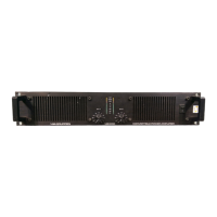
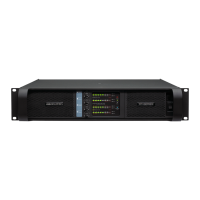
Details the function of carry handles, input attenuators, indicators, and power actuator.
Details speaker connectors, AC line cord, input jacks, phase reverse, link, and gain switches.
Describes rack mounting (2U high, EIA 19 inch) and recommends rear supports for mid-rack placement.
Explains forced air cooling, front-to-rear flow, and thermal protection muting.
Details AC mains voltage selection and warranty void if incorrect voltage is used.
Explains automatic grounding via resistor to chassis and safety of not disconnecting earth pin.
Details peak, average (1/3 power), and normal (1/8 power) operating power consumption.
Describes XLR input connectors (balanced) and their wiring convention (Pin 2 HOT).
Details TRS jacks for linking and other purposes, and input impedance.
Explains how to connect an unbalanced source by tying pin 3 to shield for minimal hum.
Details wiring for Neutrik NL4FC Speakon connectors (Pin -1 Ground, Pin +1 Positive).
Emphasizes speaker polarity, short/good quality cables, and avoiding shielded wire.
Describes independent channel operation with level attenuators controlling respective levels.
Details linking both channels for mono operation with separate level control.
Explains bridging channels for higher power mono, with specific connection and impedance requirements.
Describes phase reversal for channel B to improve power supply efficiency for specific signals.
Advises turning off power before connections, checking AC mains, rear panel switches, and lowering gain during power-up.
Explains front panel attenuators for adjusting signal level and their use in bridged mode.
Details the rear panel gain switch for input sensitivity adjustment (29dB vs. 0dB).
Describes ON LEDs, -25 dB LEDs, level bar indicators, and Clip/limit indicator.
Prevents speaker damage by limiting signals exceeding 1% THD, reducing input signal proportionally.
Mutes input signal if amplifier overheats (above 90°C), allowing cooling via Intercooler®.
Mutes input signal if high-frequency signals (>20kHz) are present at output for over five seconds.
Protects output devices from short circuits, eventually leading to thermal protection.
Protects against DC levels (>10V) on channels via fuses and crowbar protection.
Explains the Intercooler™ heat sink design for efficient cooling and thermal management.
States compliance with IEC65 electrical safety approval.
Defines EMC (Electro Magnetic Compatibility) and its requirements for emission and immunity.
Lists standards (EN, IEC) the amplifier conforms to for EMC compliance.
Guides on how to check and select the correct mains voltage (115/230V) for the amplifier.
Covers routine cleaning of the front grill and recommending professional servicing every 3 years.
Addresses issues like no output, thermal protection, and non-response, with suggested checks.
Details the one-year warranty, exclusions (misuse, alteration), and limits on incidental damages.
Advises contacting local supplier for country-specific warranty information.
Provides guidance on contacting dealers or distributors for repairs and service locations.
Outlines the procedure for returning products for factory service, including return authorization.
| Brand | Lab.gruppen |
|---|---|
| Model | LAB 500 |
| Category | Amplifier |
| Language | English |