SX-01635-000, Rev. 5 10
of a resistive bridge circuit operated by six low voltage relays. Seven decades of current amplifi-
cation are available. The five decades of ranging for the detector voltage channel is accom-
plished in two stages. A resistive bridge network operated by a single relay pre-conditions the
voltage signal before it reaches the multiplexer. The second stage of ranging for the voltage
channel is accomplished in the JFET amplification circuit of the post amplifier.
The radiometer can be operated locally at the front panel of the instrument or from the host com-
puter. Local operation is achieved through the use of seven control buttons that cycle the user
through a sequence of menus. When connected to a detector and turned on, the SC-5500 takes
continuous detector readings, displaying the results in the LCD display on the front panel or
through the Windows software application on the host computer.
Detector Input
Triax connectors for two detector channels are provided on the back panel of the SC-5500. The
connector labeled Silicon/Germanium should be used for current-based detectors such as the
Labsphere SDA-050-U or the GDA-050-U photodiode assemblies. Current-based photodiodes
are the most common form of light detection today - you will use the Silicon/Germanium con-
nector for most of your applications. The SC-5500 and Labsphere photodiode detectors operate
in photovoltaic mode. The connector labeled Thermopile/Lead Sulfide/PMT should be used for
voltage-based detector systems such as the Labsphere PDA-050 photomultiplier tube. If you
have both current and voltage based detectors, you can monitor the two detector inputs by
cycling between the CAL0 and CAL1 options using the CAL function button on the SC-5500
front panel. If you need to monitor the signal input from more than one current-based detector,
you will need to purchase a DM-1000 Detector Multiplexer.
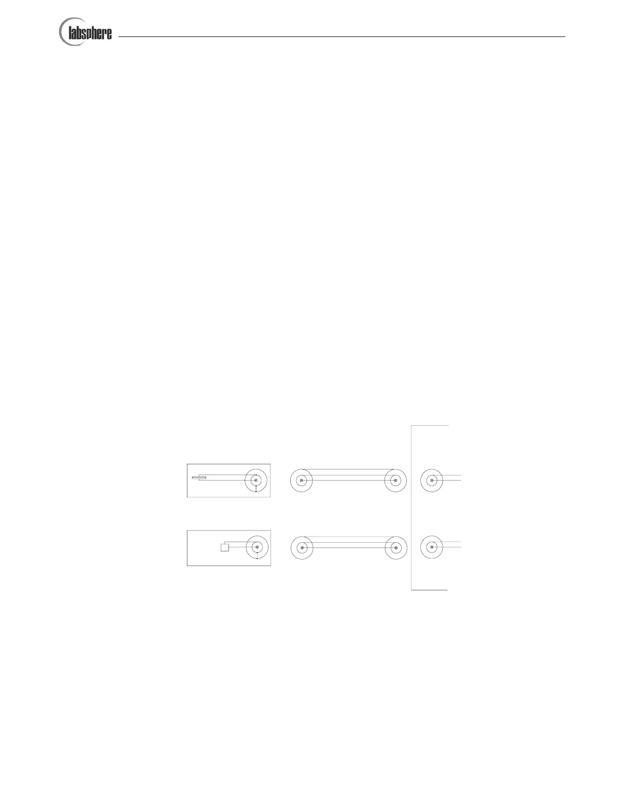
The SC-5500 detector input channels are configured to accommodate Labsphere detector assem-
blies. Labsphere photodiode detectors are wired in a manner opposite to most detectors. The
positive detector signal output from the semiconductor is wired to the center ring of the detector
+
+
-
-
SDA-050-U
PDA-050
TRIAX Cabl e
SC-5500
TRIAX Cable
Silicon
Ger mani um
Thermopile
Lead Sulfide
PMT
Figure 6. Wiring a custom detector to the SC-5500.
Artisan Technology Group - Quality Instrumentation ... Guaranteed | (888) 88-SOURCE | www.artisantg.com