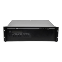
SX-01635-000, Rev. 5 12
Operating Procedures
All SC-5500 hardware features except the control of peripheral equipment are duplicated in the
standard Labsphere software applications. System operating procedures are provided in your
system instruction manual. The following procedures pertain to stand-alone operation of the SC-
5500.
Start Up
1. Press the POWER button on the front panel of the instrument. All LED indicators
will light up briefly, and go out when the system has initialized. The Power indica-
tor LED should remain on and the CAL1 default display will read detector current
in the LCD display.
2. Toggle though the Calibration Menu using the CAL button and select the calibra-
tion display required.
3. Select the automatic range feature by pressing AUTO. The green LED above will
light up.
4. To record a dark current reading, extinguish your light source and observe the
detector reading on the LCD display. Press the ZERO button to store the dark cur-
rent measurement into memory.
5. Turn on your light source and observe the readings on the LCD display. You can
stabilize the detector readout by enabling the digital filter. To do this, invoke the
DIGITAL FILTER menu option using the OPTIONS button and press the Up
∆ or
Down
∇ button.
Shutdown
When SC-5500 operation is no longer required, press the POWER button.
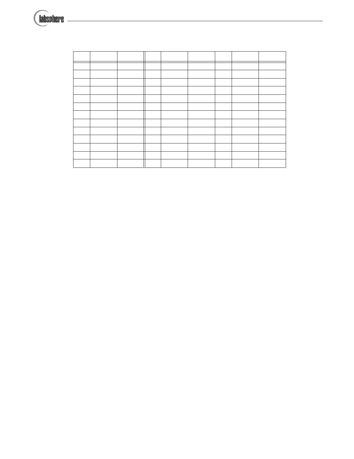
Pin Port No. Bit No. Pin Port No. Bit No. Pin Port No. Bit No.
1 1 1142 6263 5
2 1 2152 7273 6
3 1 3162 8283 7
4 1 4173 1293 8
5 1 5183 2304 1
6 1 6193 3314 2
7 1 7 20 Gnd NA 32 4 3
8 1 8 21 Gnd NA 33 4 4
9 2 1 22 Gnd NA 34 4 5
10 2 2 23 Gnd NA 35 4 6
11 2 3 24 Gnd NA 36 4 7
12 2 4 25 3 4 37 4 8
13 2 5
Table 2. Pinout and port designation for the rear panel DB37 connector.
Artisan Technology Group - Quality Instrumentation ... Guaranteed | (888) 88-SOURCE | www.artisantg.com