HUMMEL
®
01.01.2019
English / Englisch
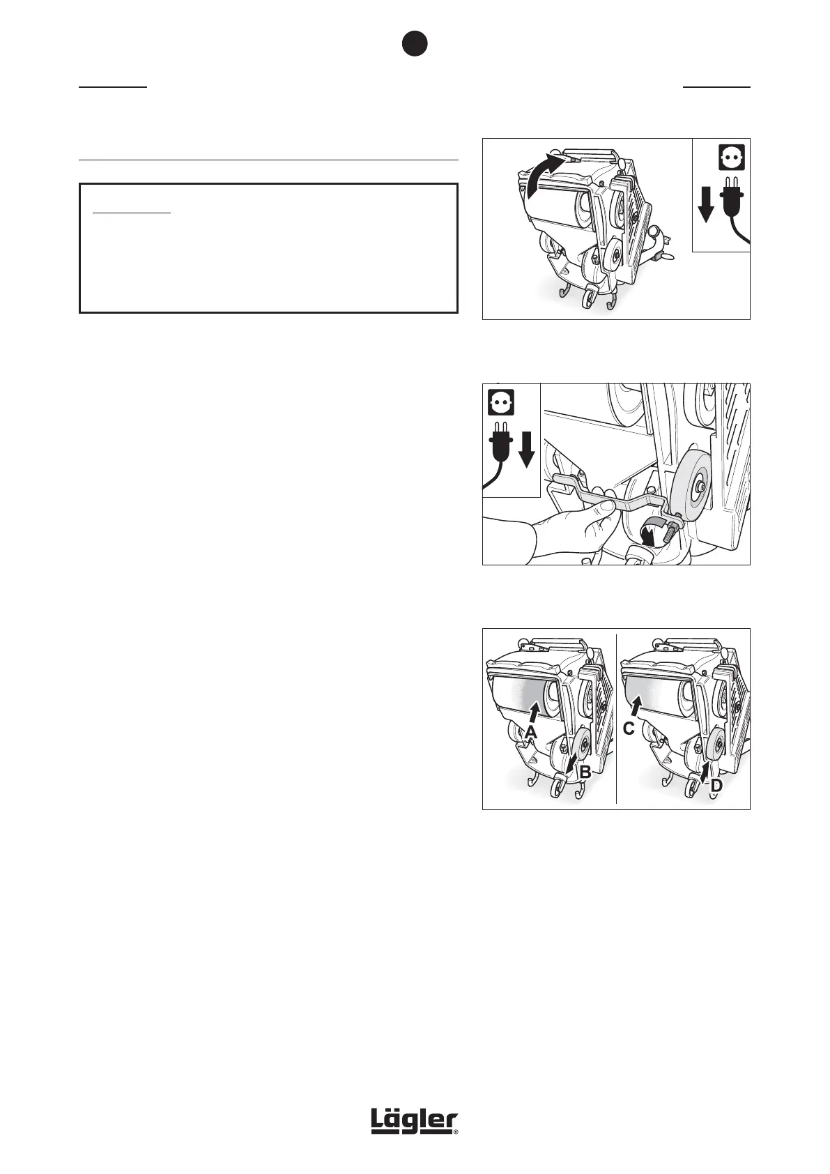
Fig. 81 Pull the power plug out of the socket! Tilt the
machine backwards. Ensure that the machine is
standing securely!
Fig. 82 Take the actual position of the adjustable wheel
using the setting fixture (right-hand wheel seen
from below).
MAINTENANCE WORK AND REPLACEMENT OF WEARING PARTS
7.4 CHECKING THE MACHINE SETTING
ATTENTION!
The best working result is achieved when the sanding drum
sands centrally! Only with this setting is it possible to avoid
the belt from sanding too deep on one side, resulting in
unwanted sanding marks!
From time to time, or as a result of incorrect transportation, it is
possible for the machine to become incorrectly adjusted. Incorrect
adjustment is indicated by one-sided sanding of the sanding drum,
which can lead to sanding tracks and complaints. Correction of
machine setting is performed as follows:
1 Lift the sanding drum off the floor by turning the lowering
lever at the handle upwards (fig. 74).
2 Switch off the machine and pull the power plug out of the
socket!
3 Tilt the machine backwards over the safety guards so that
you can see the wheel bearings (fig. 81). Ensure that the
machine is standing securely!
4 The wheel on the belt guard side can be adjusted by releasing
the tension screw. The other wheel is firmly fixed using a
screw.
5 For setting, first take the actual position of the adjustable
wheel using the setting fixture (right-hand wheel seen from
below). Position the fixture against the machine housing in
such a way that it rests not only against the machine housing
on both sides, but also at the adjustable wheel. If necessary,
turn the threaded pin of the setting device. To do this, release
the nut of the setting fixture (fig. 82).
6 If the machine is sanding more heavily on the belt guard side
(A in fig. 83), the wheel must be adjusted away from the belt
guard (direction of B in fig. 83).
If the machine is sanding more heavily on the side cover
side (C in fig. 83), the wheel must be adjusted towards the
belt guard (direction of D in fig. 83).
Now adjust the threaded pin of the setting device in the
relevant direction by the required amount.
Fig. 83 If the machine is sanding more on side A, the
wheel must be adjusted in the direction of B.
If the machine is sanding more on side C, the
wheel must be adjusted in the direction of D.
7
45


 To Next Page