Do you have a question about the Lainox NABOO NAEV101 and is the answer not in the manual?
Specifies the need for flue gas extraction or a suitable system for gas appliances.
Mandates a multiple pole isolating switch with a specific contact gap for electrical connection.
Stipulates gas supply plumbing must meet regulations and include a fast-acting shutoff valve.
Requires electrical isolating switch and water/gas shutoff valves to be easily accessible near the appliance.
Details safe lifting procedures using forklifts or jack pallets, with warnings about center of gravity.
Details requirements for type Y attachment connection, including installer-provided hardware and isolating switch.
Explains the equipotential system connection using a 10 mm² conductor for safety.
States electrical safety is guaranteed only with correct connection to an efficient earth system.
Warns to ensure neutral pin and wire alignment for correct burner operation, signalling errors electronically.
Outlines water quality parameters (hardness, pH, chlorides) crucial for preventing corrosion and scaling.
Warns against shutting, blocking, or ducting vents A and B into other pipes.
Details gas connection requirements, including pipe selection, shutoff valve, and material compliance.
Explains the procedure for leak testing gas connections using spray or foamy liquid, warning against naked flames.
Covers flue gas exhaustion for different installation types (A3, B13, B23) and temperature warnings.
Specifies required gas inlet pressure must be within indicated limits, contacting supply company if not.
Guides on measuring gas inlet pressure using a manometer connected to the pressure tap.
Instructs to check appliance and installation post-connection, verifying protective film, vents, connections, and leaks.
Guides on lighting the oven and checking for smooth burner ignition during commissioning.
Requires completion and submission of a test report for acceptance, starting the warranty period.
Emphasizes that all repair/maintenance must be performed by an authorized service agent.
Advises informing the user to immediately shut off utilities in case of breakdown or faulty operation.
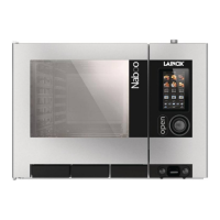
| Model | NAEV101 |
|---|---|
| Category | Oven |
| Capacity | 10 x 1/1 GN |
| Voltage | 400 V |
| Frequency | 50/60 Hz |
| Control Panel | Touchscreen |
| Temperature Range | 30°C to 300°C |
| Power Supply | Electric |
| Timer | Yes |
| Type | Electric |
| Cooking Modes | Convection |