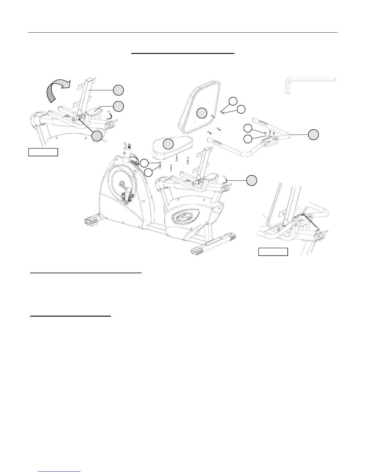
ASSEMBLY STAGE #3
Attach Seat Pads to the Seat Frame
Assembly Hardware Required:
#27 Flat Washer Qty. 8 #30 Truss Head Socket Bolt Qty. 8
#29 Truss Head Socket Bolt Qty. 4
Assembly Description:
A) Cut the packaging cable ties and lock the Adjustable Seat Back Frame (#10) into an upright position using the
Adjustment Knob (#8). (Reference FIGURE 2).
B)
Mount the Seat Pad (#6) to the Seat Slider (#11) using 4-Truss Head Bolts (#29) and 4-Flat Washer (#27).
C)
Attach the Seat Back Pad (#7) to the Adjustable Seat Back Frame (#10) using 4-Truss Head Socket Bolts (#30)
and 4-Flat Washers (#27).
D)
Attach the Handlebar Assembly (#9) to rear mounting plate of Seat Slider (#11) using 4-Truss Head Socket Bolts
(#30) and 4-Flat Washers (#27).
E)
Plug the end of the Heart Rate Cable (#22) into the rear plug-in receptacle of the Handlebar Assembly (#9).
(Reference FIGURE 3)
Assembly Note: The Seat Slider position can be adjusted using the side mounted Adjustment Knob (#12). (Not Shown)
♦ Assembly Stage #3 completed
ASSEMBLY INSTRUCTION PAGE 8
27
29
27
30
30
USE TOOL
10
9
11
8
FIGURE #2
22
FIGURE #3
27
7
6