Vega Customer Applications Manual Section 11 - Wide Range Programmable Modules
Rev. A3: October 2003 Page 46 of 48
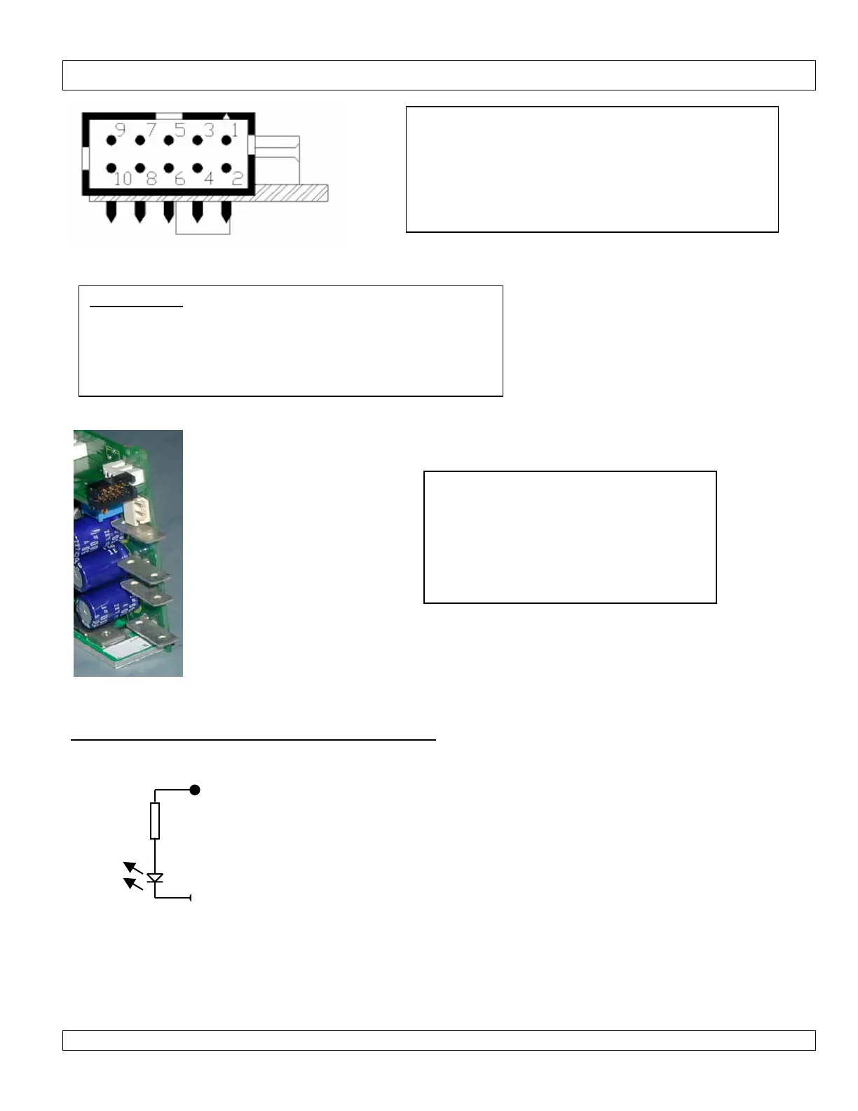
Figure 2. Pin Layout & Description.
Figure 3. Module with required option board fitted.
Module Selection, Inhibit or Enable circuit connections
When a module is inhibited, there may be up to 0.05V remaining at the outputs of the module.
Module inhibit +Ve Pins 9-10
390R
Module inhibit –Ve Pins 7-8
Internal to the module inhibit/enable is a 390ohm 1/8W
resistor and the diode of an opto-coupler.
To INHIBIT/ENABLE the module apply 2-5V between
+ve and -ve. Do not apply >6V or damage may result,
although higher voltages may be used to drive the circuit
in which case additional series resistor should be used to
limit the current. A current of 1-10mA will inhibit the
Pin 1, 2, & 3 Return circuit for pins 4, 5, & 6
Pin 4 0-5V external voltage programming pin
Pin 5 0-5V current programming pin
Pin 6 0-32kΩ Resistance programming pin
Pin 7, 8 Module Inhibit or Enable –Ve
Pin 9, 10 Module Inhibit or Enable +Ve
Abbreviations
W5: - Wide range, 5 turns
F or T: -Fixed or Tracking O/V
S or F: - Screw terminals or Fastons
V or R: -Voltage programming or Resistive programming
1-4: - Combinations of current programming and inhibit or enable
Mating connector information:
Note: housing and pins supplied with each
power supply.
Housing: Molex 51110-1060
Crimp pin: Molex 50394-8051
Hand Crimp Tool: 69008-0959 (Europe or
Japan) Or 11-01-0204(USA)