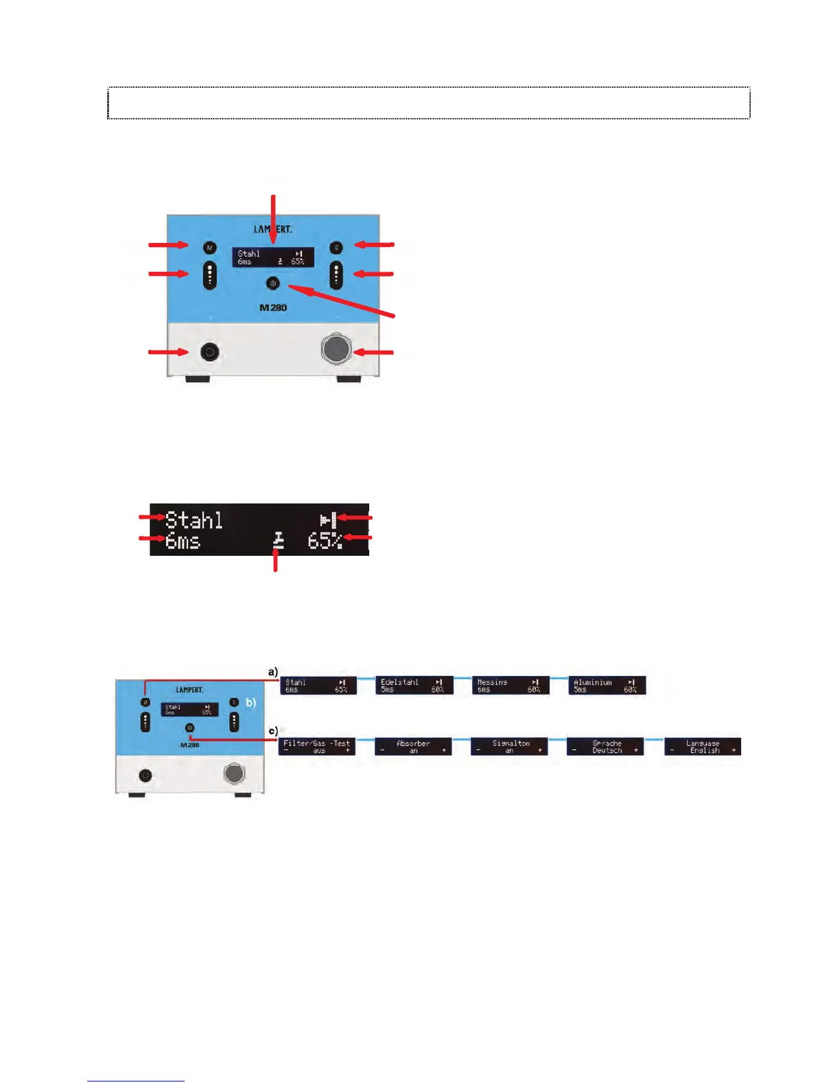
(21) DISPLAY
(22) GEOMETRY BUTTON
Preselect welding situation and pulse shape
(23) WELDING POWER (+/-) BUTTONS
(24) SETTINGS BUTTON
(25) PULSE DURATION (+/-) BUTTONS
(26) MATERIAL / METAL BUTTON
Preselect material or welding program
(27) CONNECTION SOCKET FOR HANDPIECE (-)
(2
8) SOCKET (+)
For connecting contact elements such as welding
bench, contact terminals and clamps.
DISPLAY
(30) Material or welding program
(31) Preselected welding situation (geometry)
(32) Power output as a percentage (%)
(33) Foot switch display (optional)
(34) Pulse duration in milliseconds (ms)
5.
2 EXPLANATION / OVERVIEW OF MENUS
(Fig. Schematic diagram of user levels)
ONCE IT IS SWITCHED ON, THE „M280“ STARTS UP IN ITS MAIN MENU. THE FOLLOWING USER LEVELS CAN BE
NAVIGATED AFTER PRESSING THE METAL / MATERIAL BUTTON (26):
a) Preselection of the material to be welded
b) Preselection of the welding situation (geometry)
(chapter 6.1.1)
c)
Settings can be used to modify basic settings and
la
unch various test functions.
21
28
30
31
32
33
27
23
25
26
22
24
34