4
m. Taste the beverage to verify that there is no off taste.
5. OPERATION OF THE LFS
5.1 CONNECTIONS
A. Attach 3/8” syrup hoses between syrup (BIB), syrup pump, and the unit. Inlet syrup hose, 3/8”,
attaches to left side of unit.
B. Attach CO
2 connection to syrup pump.
NOTE:
The unit recognizes the left side of the unit as syrup and right side as water.
WARNING:
FAILURE TO RUN UNIT WITHOUT WATER LINES CONNECTED WILL RESULT IN OVERHEAT
OF THE SOLENOID VALVES.
C. Attach water lines from water source or prechiller to the unit.
5.2 INITIAL POWER UP
A. Insure the switches on the unit are set to the middle (OFF) position.
B. Plug in the unit.
5.3 AUTO MODE
I.D. PANEL
A. Switch the unit into AUTO Mode. The Green power
light will come on and the valve will start
dispensing syrup and water out of the valve.
5.4 MANUAL MODE
A. Switch the unit in MANUAL Mode (this requires
holding down the switch). The Green power light
will come on and the valve will start dispensing
syrup and water out of the valve.
5.5 SETTING THE DESIRED RATIO
A. ADJUSTING WATER FLOW
The Model 145 LEV
® water flow may be adjusted
from 2.0 oz/sec (59.2 ml/sec) to 4.50 oz/sec
(133.2 ml/sec). The restricted flow adjustment plug
adjusts to a maximum flow of 3.3 oz/sec
(97.7 ml/sec).
1. Slide I.D. panel UP until flow control
adjustments are exposed (see Figure 2).
2. Remove nozzle by twisting counter clockwise and pulling down.
3. Remove diffuser by pulling down.
4. Install Lancer syrup separator (PN 54-0201, smoke, for Model 145 valves) in place of the
nozzle.
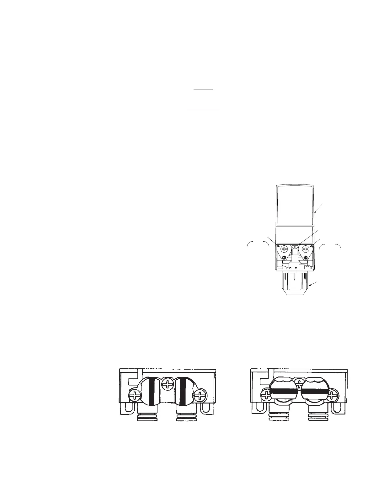
Valve Adjustment
Figure 2
Mounting Block Stems in OPEN Position
FIgure 3
Mounting Block Stems in CLOSED Position
FIgure 4
WATER
SYRUP
STEMS OPEN
WATER
SYRUP
STEMS CLOSED