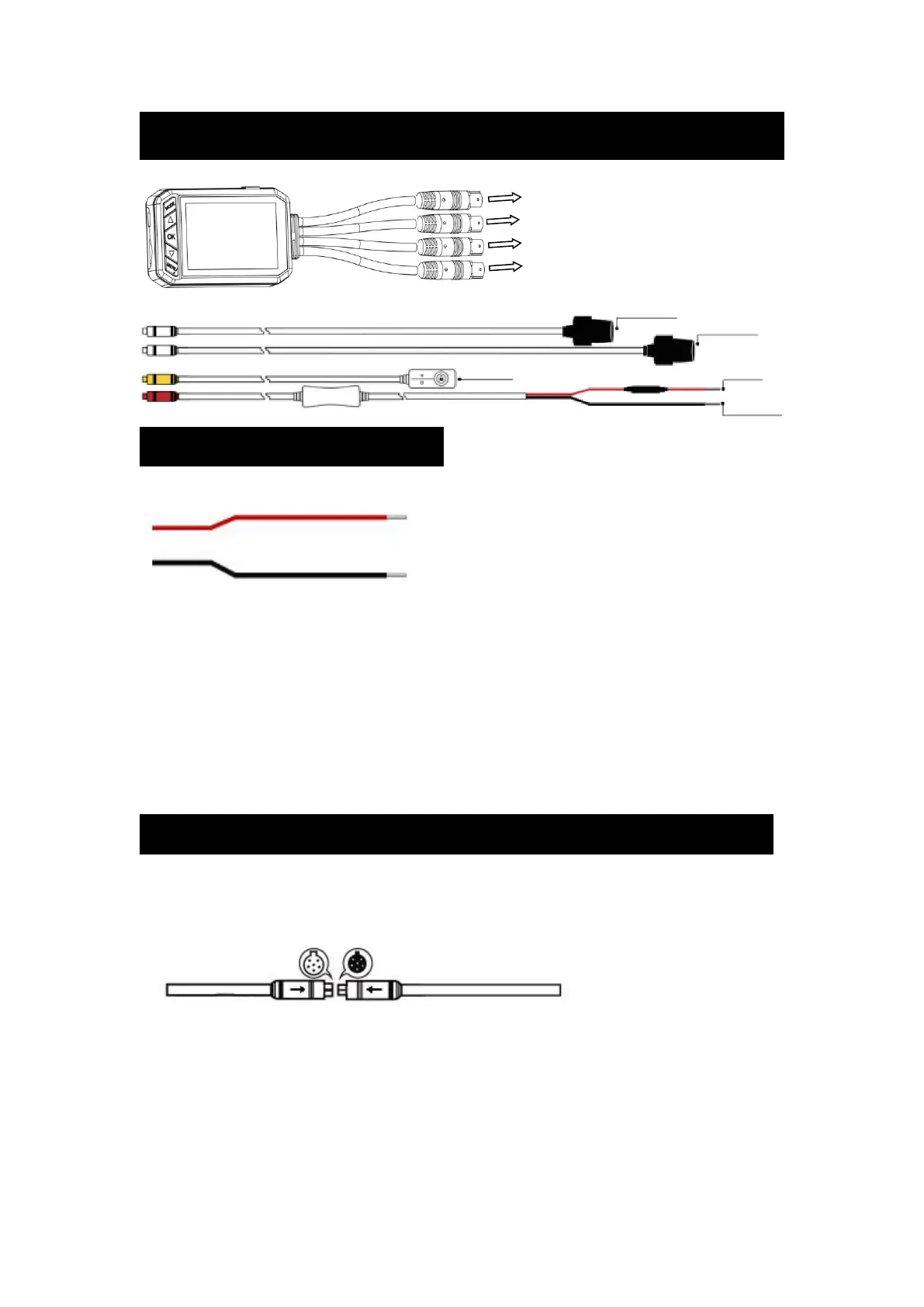
Connection Method
接続方法
How to connect by cable
※Note:
①
Please check how to remove ACC power before connecting. Check with the
Electrostatic Tester
②
If the power supply connection is incorrect, the power can not be turned off while
recording, or recording can not be performed.
Cable connection notes
⚠ Alarm:Please insert the connector into the direction of the arrow as far as possible.
Connector color description:
Red
(
Power Supply
)
Yellow(Remote Controller
)
Black
(
Camera
)
● Earth
※ Connect the ground terminal securely to the
metal body to avoid smoke / failure
● Connect to accessory power supply (+) or generates
12V voltage when the ignition key is ON


 To Next Page