Section 1: Assembly & Set-Up
Table of Contents
FDR2572 & FDR2584 Rear Discharge Grooming Mowers 310-262M11/6/18
9
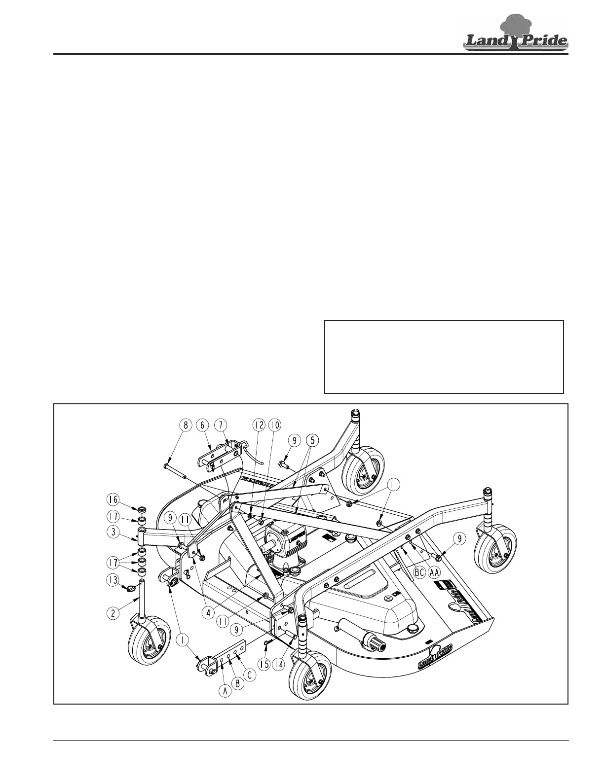
Hitch Braces Assembly
Figure 1-2
17365
Upper 3-Point Hitch Assembly
Refer to Figure 1-2:
1. Remove gauge wheel assemblies (#2), rear hitch
braces (#5), A-Frame hitch braces (#4), and lower
clevis hitches (#1) from shipping crate.
2. Attach rear hitch braces (#5) inside of rear hitch
mounting plates with 5/8"-11 x 1 3/4" GR8 bolts (#9)
and flanged locknuts (#11). Do not tighten nuts.
3. Attach A-Frame hitch braces (#4) inside front hitch
mounting plates with 5/8"-11 x 1 3/4" GR8 bolts (#9)
and flanged locknuts (#11). Do not tighten nuts.
4. Remove 5/8" x 5 1/2" bolt (#8), lock washer (#12),
and nut (#10) from upper pivoting hitch (#6). Don’t let
spacer tube (#7) fall from upper pivoting hitch.
5. Swing A-frame hitch braces (#4) up to a vertical
position. Raise rear hitch braces (#5) up and outside
of A-Frame hitch braces as shown.
6. Position upper pivoting hitch (#6) with driveline hook
hanging down as shown. Assemble upper pivoting
hitch (#6) and spacer tube (#7) in-between A-frame
hitch braces (#4) with existing bolt (#8), lock
washer (#12), and hex nut (#10).
7. Tighten 5/8"-18 GR5 bolt (#8) to the correct torque.
8. Tighten 5/8"-11 GR8 bolts (#9) to the correct torque.
Gauge Wheel Assembly
Refer to Figure 1-2:
1. Remove factory bolts from top of gauge wheel
spindles (#2).
2. Remove gauge wheel shipping brackets from gauge
wheels (#3). Keep spacers (#16 & #17) with their
respective gauge wheels.Discard shipping brackets.
3. Insert gauge wheel yoke spindles (#2) into gauge
wheel arms (#3) with three 1" spacers (#17) below
each arm. Install remaining spacers (#16 & #17)
above each arm.
4. Remove linchpins (#13) from clevis hitch pin (#1).
Secure gauge wheels (#2) to gauge wheel arms (#3)
with linchpins (#13).
Lower 3-Point Clevis Hitch Assembly
Refer to Figure 1-2:
1. Using hole “A”, attach lower clevis hitches (#1) to front
mounting plates with clevis pin (#14) and hairpin
cotter (#15) as shown.
NOTE: The 3-Point hitch system is designed for
front to back flotation when mowing on uneven
terrain. Additional field flotation and/or tractor
clearance can be obtained by mounting clevis
hitches (#1) with hole “B” or “C”. Rear brace
bars (#6) may need to be moved to holes “BC”.