Section 3: Adjustments
Table of Contents
FDR2572 & FDR2584 Rear Discharge Grooming Mowers 310-262M11/6/18
15
Leveling the Mower
Refer to Figure 4-1:
1. Set lower hitches and upper floating hitch, as shown.
2. Start tractor and raise mower while watching tractor
draw bar (if not removed) to make sure it does not
interfere with driveline and mower.
3. Slowly lower mower until gauge wheels touch ground
and the lower 3-Point hitch bars are parallel to the
ground in floating position. Set tractor 3-Point stop.
4. Set park brake, turn off tractor, and remove key.
5. Rotate blades parallel to direction of travel.
6. Measure clearance from the blade cutting edge to the
ground at the front and rear of the mower. These two
measurements should be equal or the blade at the
front should not be more than 1/2" lower than the
blade at the rear. The rear blade should not be lower
than the front blade.
3-Point Hitch
Figure 4-1
Cutting Height Adjustment
WARNING
!
To avoid serious injury or death:
• Always shut tractor down using “Tractor Shutdown
Procedure” provided in this manual before dismounting
tractor.
• Wear a pair of gloves when checking cutting height. Avoid
direct contact with cutting edge of blade.
1. Using the tractor, raise mower off the ground and
support under it with secure blocking to keep the
mower from drifting down during maintenance.
2. Holding wheel and yoke assembly up, remove quick-
lock pin from top of gauge wheel spindle.
3. Position full length spacers and half spacer as
required. All spacers on top of spindle tube allow for
approximately 3/4" cutting height. Adjustments range
from 3/4" to a maximum of 5-1/4" in 1/2" increments.
Refer to “Leveling the Mower” on this page.
NOTE: Tractor & mower should be on level ground.
17366
3-Point Hitch Adjustments
Refer to Figure 4-1:
The 3-Point hitch system on this mower has been
designed for front to back flotation when mowing on
uneven terrain. Adjust tractor’s top link to place the upper
hitch pin vertically above the lower hitch pins as shown.
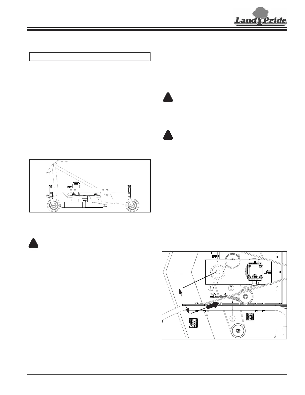
Belt Tension
Refer to Figure 4-2:
WARNING
!
To avoid serious injury or death:
Excessive belt tension can lead to premature damage/
breakage of belt and drive component and is a safety hazard
to operator and bystanders.
CAUTION
!
To avoid minor or moderate injury:
The Belt drive system is under spring tension. Use care when
servicing the spring tensioned system to avoid bodily harm.
1. To check tension apply force at arrow A with a
tension tester and deflect the belt 1/4". The force
required to get this deflection should range from
7 to 10 lbs.
2. To adjust belt tension, adjust eyebolt (#1), as
necessary. This adjustment will increase or decrease
the tension on spring (#2). If more tension is needed
than the eyebolt can adjust take the tension
spring (#2) to next link in the tension chain (#3).
3. Excessive tension on the belt may lead to premature
failure of belt and drive components. Excessive
tension on the belt may also lead to a safety hazard
to the operator or bystanders. Not enough tension on
the belt may lead to premature failure of the belt due
to excessive slipping.
Belt Tension
Figure 4-2
17362
1/2 SPAN
A
Section 3: Adjustments