User Guide User Guide
Page 7 Page 7
Fibroptic Thermometer
Fibroptic Thermometer
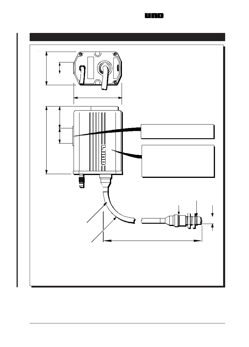
2.0 INSTALLING THE UNO FIBROPTIC THERMOMETER
Fig. 3 UNO Fibroptic thermometer installation dimensions UN970324
25/ 1.0 54.5/ 2.15
158/6.22
114/4.49
25/0.98
80.5/3.17
Minimum bend
Light guide length
All dim ensions in mill imetres/inches
SERIAL No.
TYPE:
18/0.71
radius 50/1.97
ingress
Recommended orientation of
therm om eter to prev ent
of water, and build up of dirt etc.
on electrical and lightguide
connectors
Mounting pad - 2 holes ¼" BSW
7/0.3 deep on 25/ 1.0 centres
Spacer
thread
M22 x 1.5
Approx. 160/6.30
required for optic head removal
L10 = 1000/39.37
L20 = 2000/78.74
L35 = 3500/137.80