User Guide User Guide
Page 11 Page 11
Fibroptic Thermometer
Fibroptic Thermometer
3.0 USING THE THERMOMETER
Before final installation of the thermometer, the internal controls (i.e. Emissivity, Averager
response speed or Peak picker decay rate) must be set to match the particular measurement
location. This involves removing the internal chassis from the thermometer cover.
3.1 Removing the chassis from the thermometer cover
CAUTION
Ensure that the thermometer is disconnected from the
power supply before removing the chassis from the
cover.
Ensure that the thermometer is dismantled in a clean
laboratory or office environment.
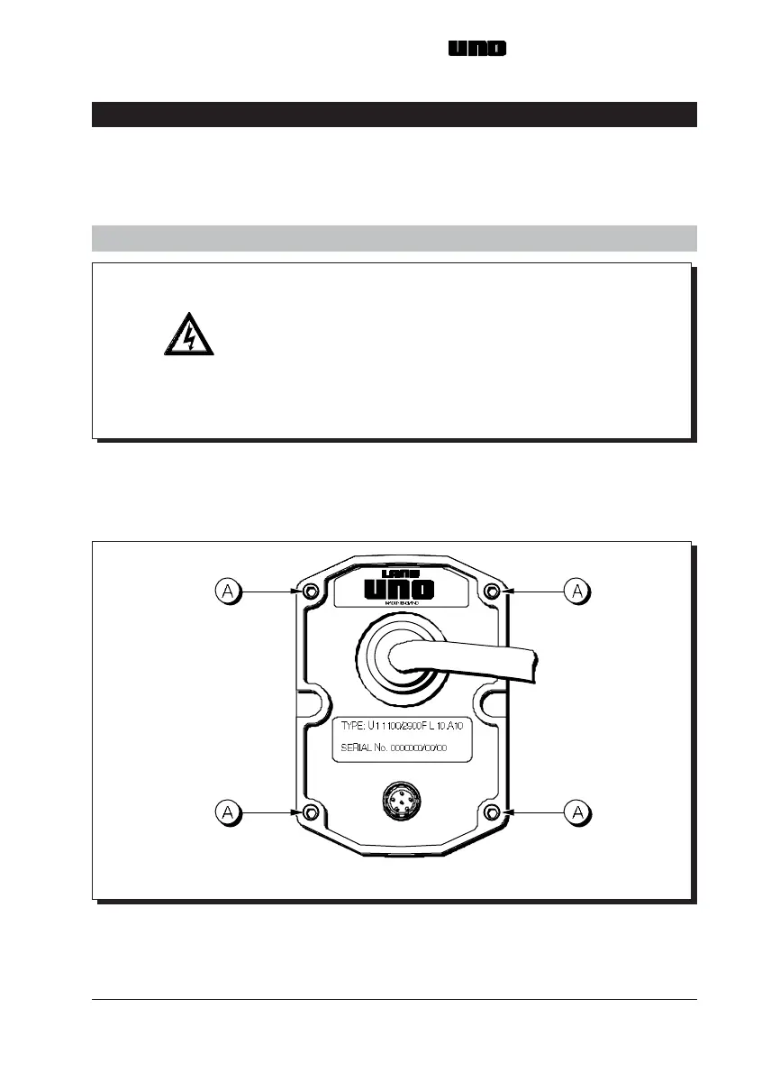
(i) Refer to Fig. 5. Use the 2.5mm Hex screw driver to loosen the four captive
screws (A).
(ii) Slide the chassis out of the thermometer cover.
Fig. 5 Location of thermometer cover securing screws UN970329
3.0 USING THE THERMOMETER
Before final installation of the thermometer, the internal controls (i.e. Emissivity, Averager
response speed or Peak picker decay rate) must be set to match the particular measurement
location. This involves removing the internal chassis from the thermometer cover.
3.1 Removing the chassis from the thermometer cover
CAUTION
Ensure that the thermometer is disconnected from the
power supply before removing the chassis from the
cover.
Ensure that the thermometer is dismantled in a clean
laboratory or office environment.
(i) Refer to Fig. 5. Use the 2.5mm Hex screw driver to loosen the four captive
screws (A).
(ii) Slide the chassis out of the thermometer cover.
Fig. 5 Location of thermometer cover securing screws UN970329