User Guide User Guide
Page 10 Page 10
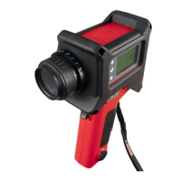
Fibroptic Thermometer
Fibroptic Thermometer
(iii) If the thermometer is to be installed in a location where the ambient
temperature is within the range specified for the thermometer, it can be
mounted using the two tapped holes on the mounting pad. Either hole can
be used for direct tripod mounting.
(iv) Choose a location for the thermometer which is free from excess
vibration, dirt and moisture.
(v) It is important that, in order to prevent any possibility of water ingress into
the electronics/detector module, the thermometer is mounted in the
orientation shown in Fig. 3.
(vi) It is recommended that, in order to minimise the build-up of dirt etc. on the
electrical and lightguide connectors, the thermometer is mounted such that
these connectors are on the underside (as shown in Fig. 3).