User Guide User Guide
Page 16 Page 16
Fibroptic Thermometer
Fibroptic Thermometer
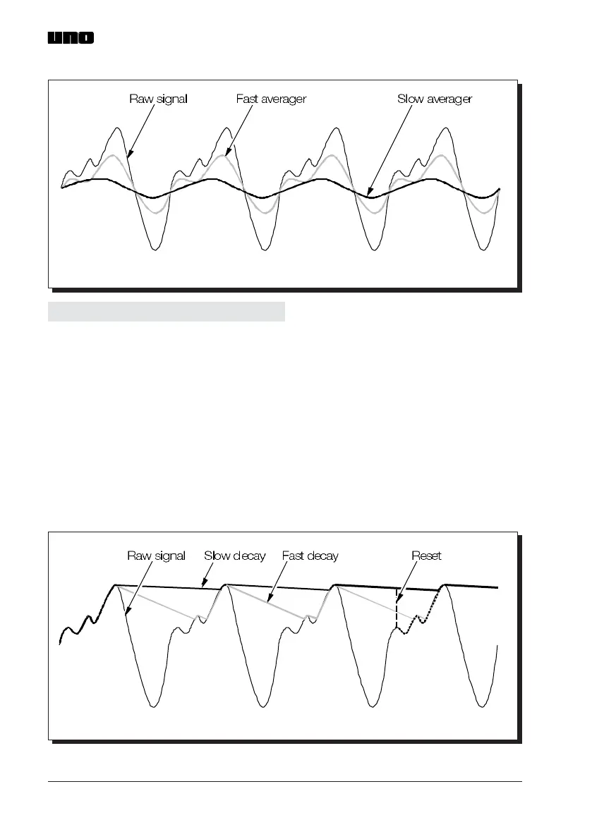
Fig. 10 Typical output of Averager time function UN970316
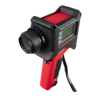
3.4.2 Peak picker
The Peak picker time function is selected by setting switch, SW5, to position 2 (i.e. right).
The Peak picker decay rate can be set, via switch SW4, to any one of the ten values
shown in Fig. 9.
The CMD (Command) input, available between pins 3 and 7 of the thermometer
electrical connector, enables remote resetting of the Peak picker time function. (Refer
to Section 3.8.1). When the CMD input is open circuit, the Peak picker operates under
the control of switches SW4 and SW5. When the CMD input is short circuit, the Peak
picker function is RESET and the output signal reverts to tracking the input, regardless
of the setting switches SW4 and SW5.
A graphical explanation of the Peak time function is given in Fig. 11.
Fig. 11 Typical output of Peak picker time function UN970317
Fig. 10 Typical output of Averager time function UN970316
3.4.2 Peak picker
The Peak picker time function is selected by setting switch, SW5, to position 2 (i.e. right).
The Peak picker decay rate can be set, via switch SW4, to any one of the ten values
shown in Fig. 9.
The CMD (Command) input, available between pins 3 and 7 of the thermometer
electrical connector, enables remote resetting of the Peak picker time function. (Refer
to Section 3.8.1). When the CMD input is open circuit, the Peak picker operates under
the control of switches SW4 and SW5. When the CMD input is short circuit, the Peak
picker function is RESET and the output signal reverts to tracking the input, regardless
of the setting switches SW4 and SW5.
A graphical explanation of the Peak time function is given in Fig. 11.
Fig. 11 Typical output of Peak picker time function UN970317