LMH Series Rotary Lasers • 19
6.1.2 Upright Position Calibration - X axis (LMH, LMH-C, LMH-GR)
1: Keep the unit in its current position.
Power Off the unit.
2: Power On the unit while holding the ADS
button down. You will know if Calibration
mode is activated when the Battery Low and
ADS LEDs fl ash alternately. Then, the ADS LED
will remain lit; this indicates that the unit is
calibrating within the X axis (Fig. 11).
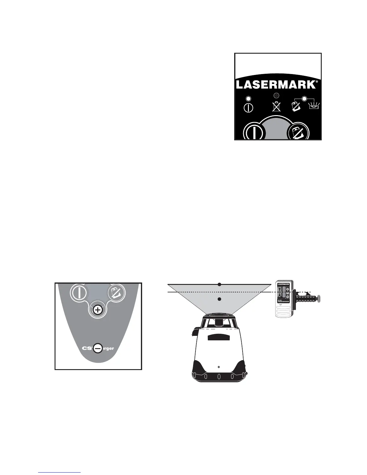
3: Locate the position of the two calibration
buttons as shown in (Fig. 12), on the
LMH-GR the UP and DOWN ARROW buttons change the axis
increments. The upper button will produce a positive (+)
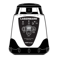
4: You must raise or lower the beam to center between points A and B
on the wall (Fig. 13). The unit will react to “+” and “–” input within the
X+ quadrant, with each single increment moving the beam
approximately ±
1
/
16
" at 100 feet. If B is below A, increase the increment
(+). If B is above A, decrease the increment (-).
5: The adjustments are automatically saved. You must now repeat the
peg test (6.1) to insure you have made the correct calibration. Repeat
calibration if necessary. You must allow time for the calibration change
to be saved in memory.
Fig. 11
Calibration Mode
X Axis active
LMH
ANTI-DRIFT
SYSTEM
POWER
MANUAL
Automatic Self-Leveling
Rotary Laser
LMH
Calibrated
A
B
Fig. 13
X+ facing
the wall
LMH and LMH-C
Fig. 12