20 • LMH Series Rotary Lasers
6.1.3 Upright Position Peg Test and Calibration - Y axis (LMH,
LMH-C, LMH-GR)
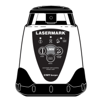
If you wish to test the Y axis at the same time as the X axis, simply
keep the unit on from when you tested the X axis and rotate the unit
90° so that the front of the unit is facing the wall. Press the ADS
button to turn the ADS LED off; you are now calibrating within
the Y axis (Fig. 14); follow 6.1, steps 2 through 4.
If you are testing the Y axis at a later time than the X axis, mount the
LaserMark
®
on a tripod and place approximately 100 feet (30m) away
from a wall, with the handle (Y– quadrant) of the unit facing the wall;
follow 6.1, steps 2 through 4.
Calibrate as in 6.1.2, adjusting “+” and “–” input as necessary within the
Y+ quadrant (Fig. 15).
If you are unable to calibrate the unit, or if the difference between points A and B is
too great to calibrate within the range of the unit, please contact CST/Berger or an
authorized service center for assistance.
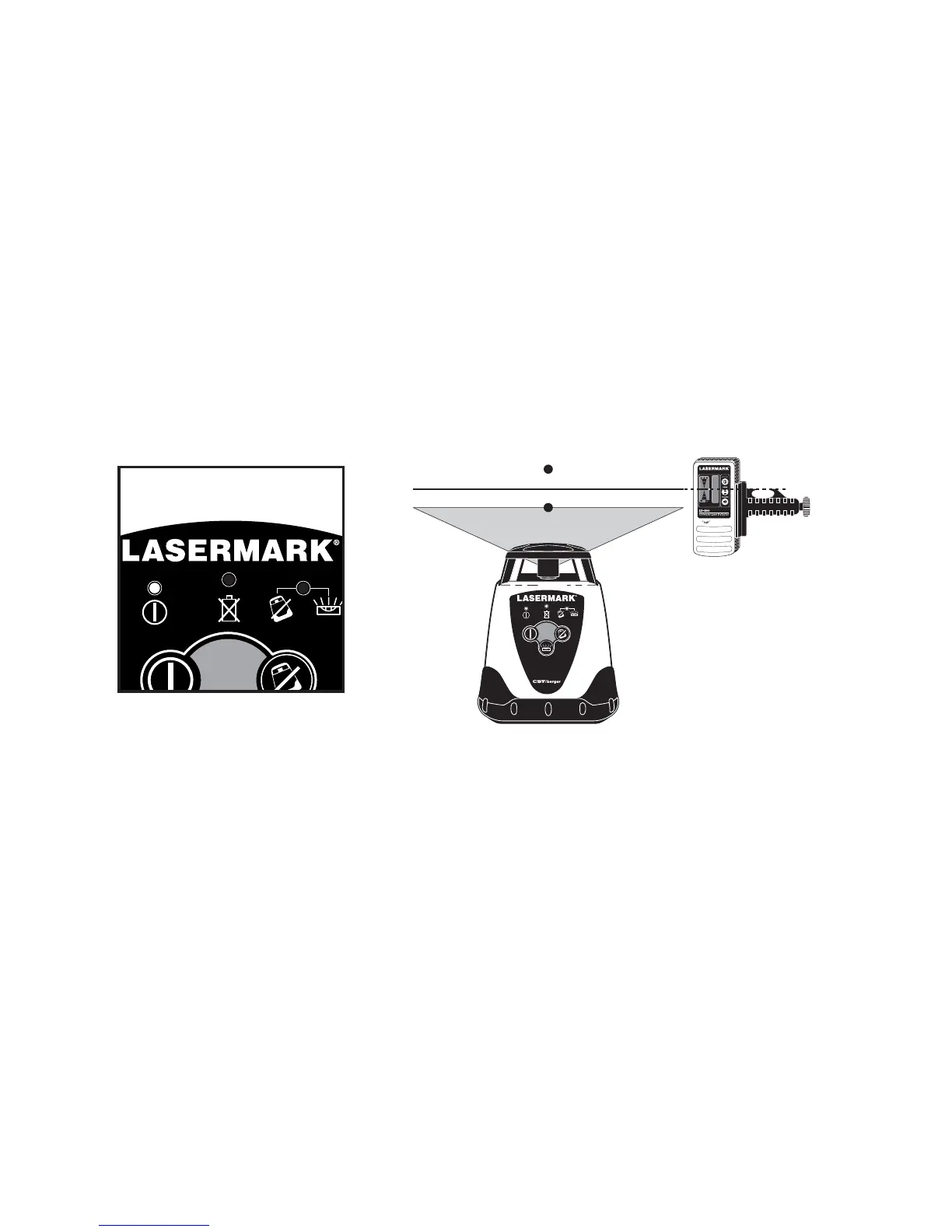
Fig. 14
Calibration Mode
Y Axis active
LMH
B
A
Calibrated
ANTI-DRIFT
SYSTEM
POWER
MANUAL
Automatic Self-Leveling
Rotary Laser
LMH
Fig. 15
Y+ facing
the wall